Installation Dometic Interact
12
EN
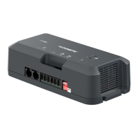
3.4 Installing the DB-201
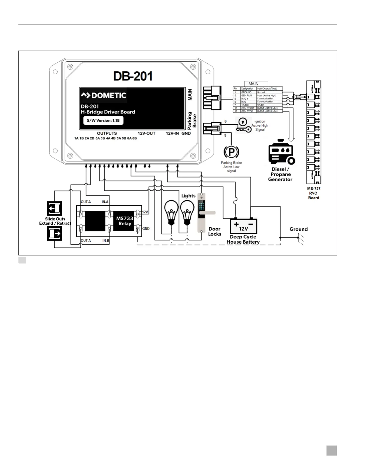
14 DB-201 Installation Example
To install the DB-201 driver board:
1. Connect the 12 VDC positive wire from the battery to
the 12V-IN port on the load box using a 20 A fuse.
2. Connect the ground wire to the negative side of the
battery.
3. Connect the lights, locks, and slide-outs to the
appropriate output pins on the load box.
4. Use an MS-733 relay for the slide-outs:
a. Connect the 12 VDC and ground wires on the
input side of the relay.
b. Connect the slide-in and slide-out wires from the
outputs of the load boxes to the middle pins of
the relay.
c. Connect the two wires of the mechanical slide-
out motor to the output side of the relay.
5. Connect the generator inputs and outputs between
the load box connector and the RVC network.
6. Connect the parking brake and ignition inputs to the
load box. These input signals are used as safety
interlocks for the awnings and AGS lockout
operation.
I
All of the positive wires from the lights and locks
should be routed to the output pins where the
negative wires go to the negative terminal strip.
 Loading...