[page 4] | gpelectric.com
1.1 INTRODUCTION
A Solar Controller (or Charge Controller / Regulator) is an essential component of your photovoltaic solar system. The Controller
maintains the life of the battery by protecting it from overcharging. When your battery has reached a 100% state of charge, the
Controller prevents overcharging by limiting the current owing into the batteries from your solar array.
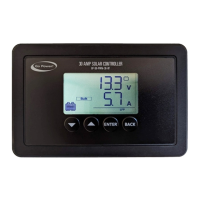
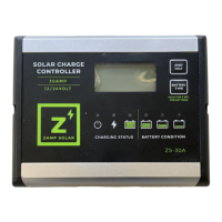
The GP-PWM-30-SB uses Pulse Width Modulation (PWM) technology and a unique four stage charging system that includes
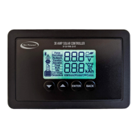
an optional equalize setting to charge and protect your battery bank. The GP-PWM-30-SB features an LCD digital display that
shows the charge current of the solar array, battery voltage and battery state of charge.
1.2 SYSTEM VOLTAGE AND CURRENT
The GP-PWM-10-FM is intended for use at 12 VDC nominal system voltage and is rated for a maximum continuous DC input
current of 12.5A and input voltage of 35VDC.
Per the National Electric Code (NEC) article 690.7 and 690.8, PV module nameplate ratings at Standard Test Conditions (STC)
must be multiplied by required values (typically 1.25 for both voltage and current) to obtain the true voltage and continuous
current available from the module.
Applying the NEC factors, the maximum allowable nameplate PV Panel rated Isc is 10A (10A x 1.25 = 12.5A), and the maximum
voltage, Voc is 28VDC (28VDC x 1.25 = 35VDC).
The voltage and current ratings of all equipment connected to PV panels must be capable of accepting the voltage and current
levels available from PV panels installed in the eld.
1.3 BATTERY TYPE
The GP-PWM-30-SB is suitable for use with lead acid batteries (vented, GEL, or AGM) as well as some lithium iron phosphate
(LiFePO4) batteries that are supplied with a Battery Management System (BMS).
1.4 LOW VOLTAGE DISCONNECT FUNCTION (USB PORT)
To protect the battery against over-discharge this function automatically switches o the USB output port when battery voltage is
lower than 11.0 VDC. As soon as the battery reaches a voltage of 12.8 VDC the USB output port is switched on again.
1.5 REGULATORY INFORMATION
1. INSTALLATION OVERVIEW

 Loading...