gpelectric.com | [page 7]
• Flathead Screwdriver (for wire terminals)
• Philips Screwdriver (for mounting screws)
• Wire Cutter /Stripper
If the GP-PWM-30-SB Controller was purchased with a Go Power! Solar Power Kit, then UV resistant wire is included. For
instructions regarding the Go Power! Solar Power Kit installation, please refer to the Installation Guide provided with the Kit.
4. CHOOSING A LOCATION
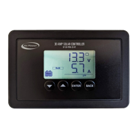
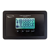
TheGP-PWM-30-SBisdesignedtobemountedushagainstawall,outofthewaybuteasilyvisible.
The GP-PWM-30-SB should be:
• Mounted as close to the battery as possible
• Mounted on a vertical surface to optimize cooling of the unit
• Indoors, protected from the weather
In an RV, the most common controller location is above the refrigerator. The wire from the solar array most commonly enters the RV
through the fridge vent on the roof or by using the Go Power! Cable Entry Plate (sold separately) that allows installers to run wires
through any part of the roof. PV connections should connect directly to the controller. Positive and negative battery connections must
connect directly from the controller to the batteries. Use of a positive or negative distribution bus is allowed between the controller
and battery as long as it is properly sized, electrically safe and an adequate wire size is maintained.
5. INSTALLATION INSTRUCTIONS
1.
Prepare for mounting.Usethetemplateprovidedonpage17tomarkthefourmountingholesandthecuttinglineforush
mounting your controller.
2. Complete the installation of the solar modules. If this GP-PWM-30-SB was purchased as part of a Go Power! Solar Power
Kit, follow the Installation Guide provided. Otherwise, follow manufacturer’s instructions for solar module mounting and wiring.
3.
Select wire type and gauge. If this GP-PWM-30-SB was purchased as part of a Go Power! Solar Power Kit, appropriate wire
type, gauge, and length is provided. Please continue to Section 6, “Operating Instructions.” If the GP-PWM-30-SB was purchased
separately, follow the instructions included here.
Wire type is recommended to be a stranded copper UV-resistant wire. Wire fatigue and the likelihood of a loose connection are greatly
reduced in stranded wire compared to solid wire. Wire gauge should be able to sustain rated current and minimize voltage drop.
Wire Strip Length
Strip wires to a length of approximately 3/8 in (9 mm, as per strip gauge).
Suggested Minimum Wire Gauge
(Cable length 25 ft. max. from solar array to battery bank)
80 Watt Solar Module #10 Wire Gauge
100 Watt Solar Module #10 Wire Gauge
160 Watt Solar Module #10 Wire Gauge
170 Watt Solar Module #10 Wire Gauge
190 Watt Solar Module #10 Wire Gauge
IMPORTANT: Identify the polarity (positive and negative) on the cable used for the battery and solar module. Use colored wires or
mark the wire ends with tags. Although the GP-PWM-30-SB is protected, a reverse polarity contact may damage the unit.
Wiring the GP-PWM-30-SB. Wire the GP-PWM-30-SB according to the wiring schematic in Section 6. Run wires from the solar array and
the batteries to the location of the GP-PWM-30-SB. Keep the solar array covered with an opaque material until all wiring is completed.
3. TOOL AND MATERIALS NEEDED
Note

 Loading...