[page 8] | gpelectric.com
6. WIRING DIAGRAMS
IMPORTANT: All wiring must be in accordance to National Electrical Code, ANSI/NFPA 70. Always use appropriate circuit protection
on any conductor attached to a battery.
4. Connectthebatterywiringtothecontrollerrstandthenconnectthebatterywiringtothebattery.
5. Torque all terminal screws per the following:
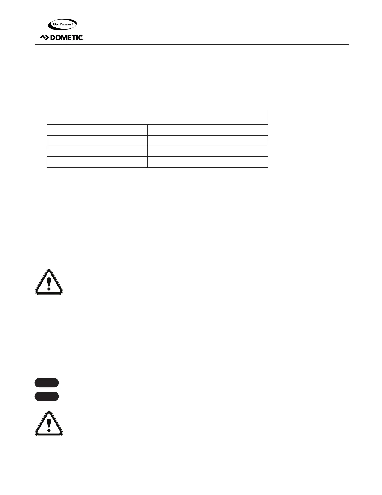
Stranded Copper 90°C Wire
Wire Size AWG Rated Torque (in-lbs)
14 20
12 20
10 20
With battery power attached, the controller should power up and display information. Connect the solar wiring to the controller and
remove the opaque material from the solar array. The negative solar array and battery wiring must be connected directly to the con-
troller for proper operation. Do not connect the negative solar array or negative battery controller wiring to the chassis of the vehicle.
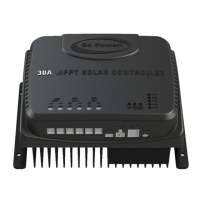
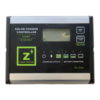
6. Mounting the GP-PWM-30-SB. Mount the GP-PWM-30-SB to the wall using the included four mounting screws.
IMPORTANT: You must set the battery type on the GP-PWM-30-SB before you begin to use the controller (follow steps in Section 7).
The default battery setting is for AGM/LiFePO4 batteries.
Congratulations, your GP-PWM-30-SB should now be operational. If the battery power is low and the solar array is producing power,
your battery should begin to charge.
7. Re-torque: After 30 days of operation, re-torque all terminal screws to ensure the wires are properly secured to the controller.
WARNING: This unit is not provided with a GFDI device. This charge controller must be used with an external GFDI device
as required by Article 690 of the National Electric Code for the installation location.
6. WIRING DIAGRAMS
IMPORTANT: This diagram is valid only for version 1.5 and newer. Version 1.4 and older have dierent terminal locations.
The GP-PWM-30-SB Maximum 37.5A rating is based on a 30 amp total maximum short circuit current rating (Isc) from the parallel
solarmodulesnameplateratings.TheNationalElectricCodespeciesthePVequipment/systemratingtobe125%ofthemaximum
Isc from the PV module nameplate ratings (1.25 times 30 = 37.5A). Use the wiring diagram (below) to connect your battery to the
battery terminals on the solar controller. First, connect the battery to the controller, and then connect the solar panel to the controller.
The fuse or breaker used should be no larger than 50 amps.
The controller will not work unless there is a battery connected to the battery terminals with at least 9V.
WARNING: When the photovoltaic (solar) array is exposed to light, it supplies a dc voltage to this equipment
Note
Note

 Loading...