gpelectric.com | [page 9]
7. OPERATING INSTRUCTIONS
7. OPERATING INSTRUCTIONS
7.1 SYSTEM VOLTAGE AND CURRENT
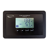
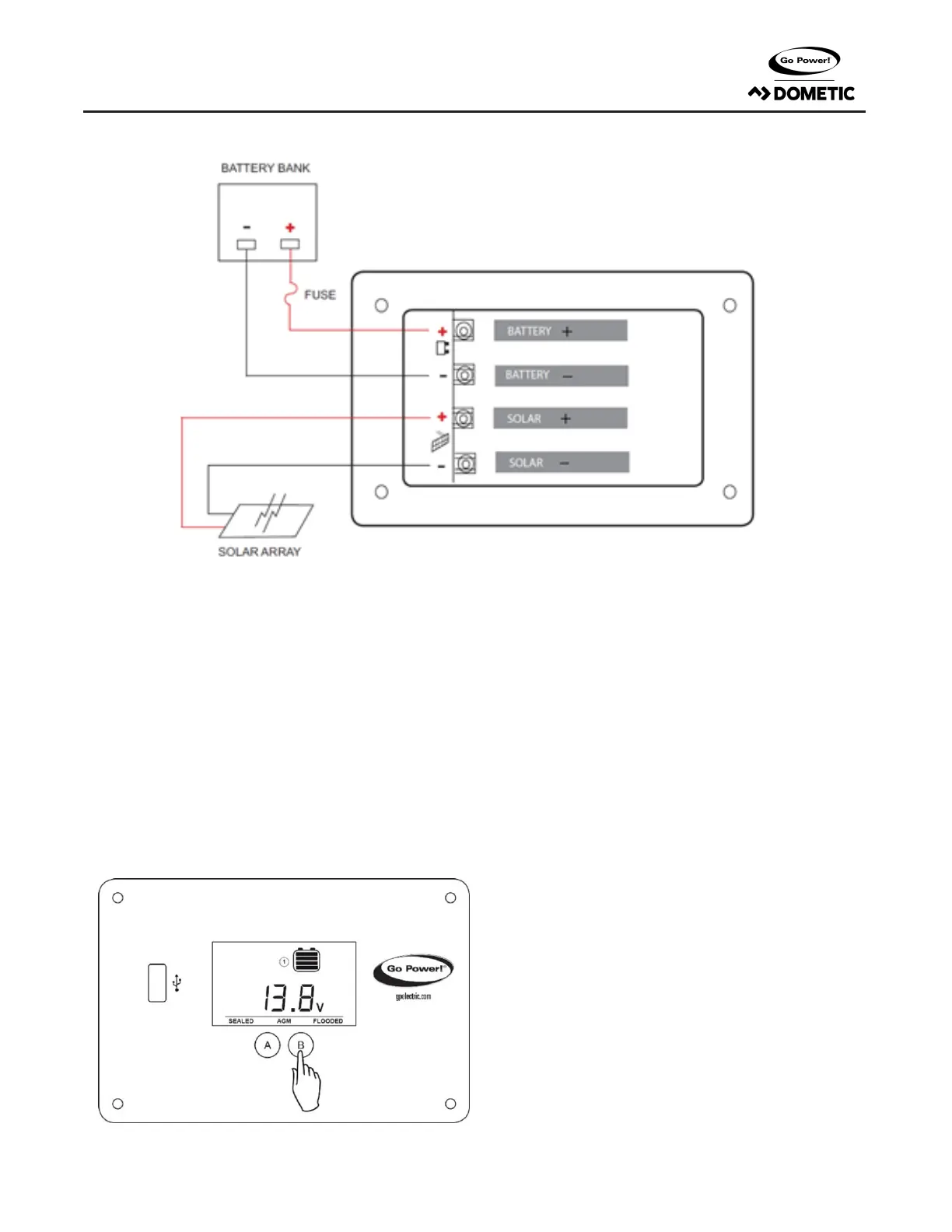
When the GP-PWM-30-SB is connected to the battery, the controller will go into Power Up mode.
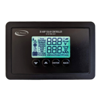
Icons Displayed: All segments of the numerical display; backlight blinks. Depending on the battery voltage when the GP-PWM-30-SB Power Up
occurs,thecontrollermaydoaBoostChargeorquicklygointoFloatCharge.TheChargingProleselectedwillcommencethefollowingdayaftera
PowerUp(refertotheChargingProleChartonpage11formoredetails).
7.2 SETTING THE BATTERY CHARGING PROFILE
Toselectthebatterychargingprole,pressandholdtheB Button. This
willcausethecurrentbatterytypetoash.
Then,presstheBButtontotogglethroughtheproleoptions:Sealed/
Gel, AGM/LiFePO4 or Flooded.
Toconrmthebatteryprole,pressandholdtheA Button for 3 seconds.
Non-volatile memory: Any settings made on the GP-PWM-10-FM will be
saved even when the power has been disconnected from the controller.
RefertotheBatteryChargeProleChartbelowfordetailsoneachprole.
30 AMP PWM SOLAR CONTROLLER

 Loading...