12
Components
2.0 Components
2.1 Power modules
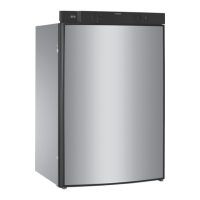
2.1.1 Power module RM 8xx1 ( MES)
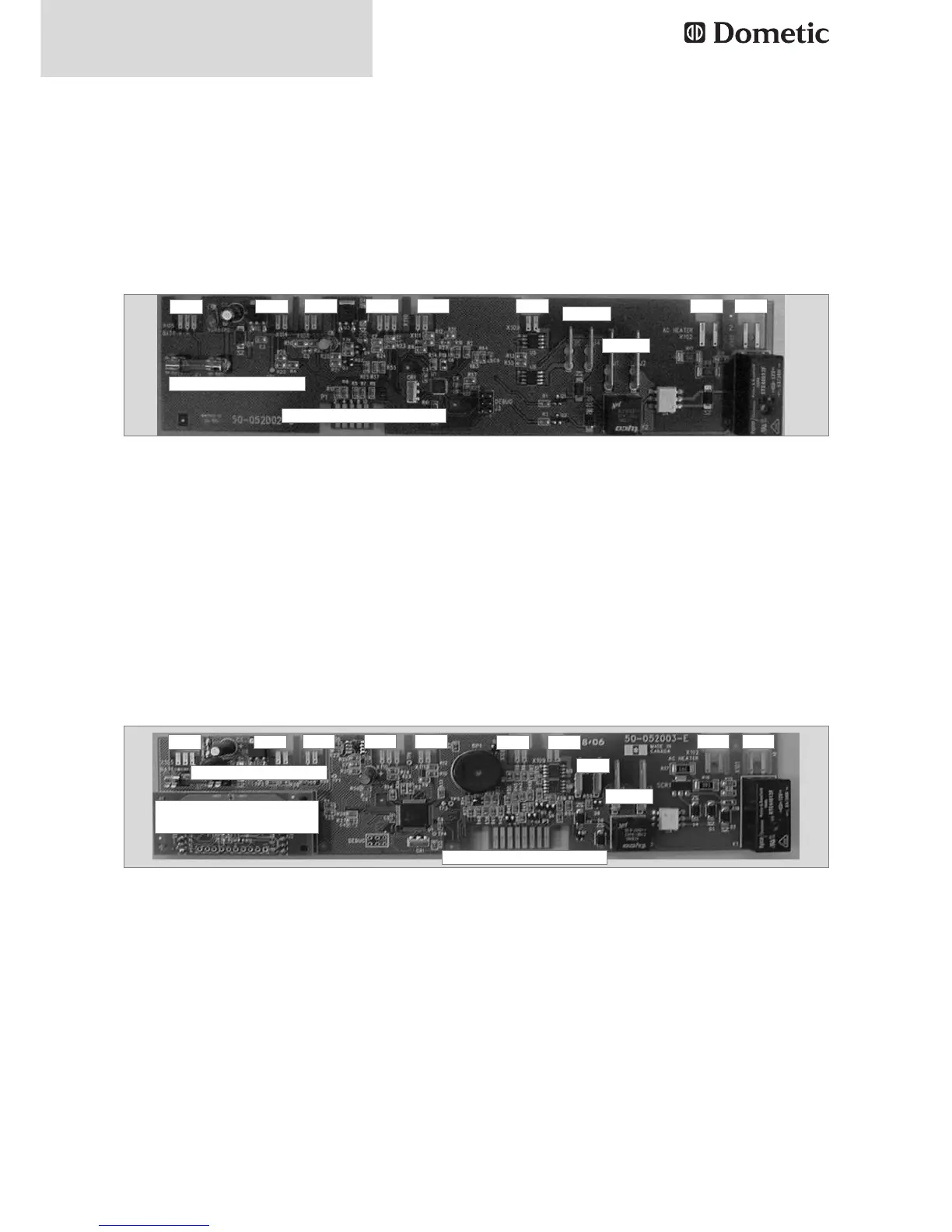
2.1.2 Power module RM 8xx5 ( AES)
X105 = 12 V Supply / - Wiring Recognition of heating element
X114 = Reed switch or alt. electr. lock
X108 = Temperature sensor (NTC)
X110 = Connection burner control device (+/-, failure)
X111 = alt. 2. electr. Lock or reed switch
X109 = Lighting
J4/J5 = Frame heating
J1 = +12 V IN for heating element
J2 = +12 V Heating element
X102 = Heating element mains power
X101 = mains power inlet *Fuse 12V
Fig. 17
X105 = 12 V Supply / - Wiring Recognition of heating element
X114 = Reed switch or alt. electr. lock
X108 = Temperature sensor (NTC)
X110 = Connection burner control device (+/-, failure)
X111 = alt. 2. electr. Lock or reed switch
X109 = Lighting
J4/J5 = Frame heating
J1 = +12 V IN for heating element
J2 = +12 V Heating element
X102 = Heating element mains power
X101 = mains power inlet *Fuse 12V
Fig. 18
X105
Fuse* 1A / 250V
X114
X108 X110 X111 X109 X102 X101
Connection to display
J4/J5
J1/J2
X105
Fuse* 1A / 250V
X114
X108 X110 X111
X109
X109
X106
X102 X101
Connection to display
RF Module for RMCD
remote control
J1/J2
 Loading...