15
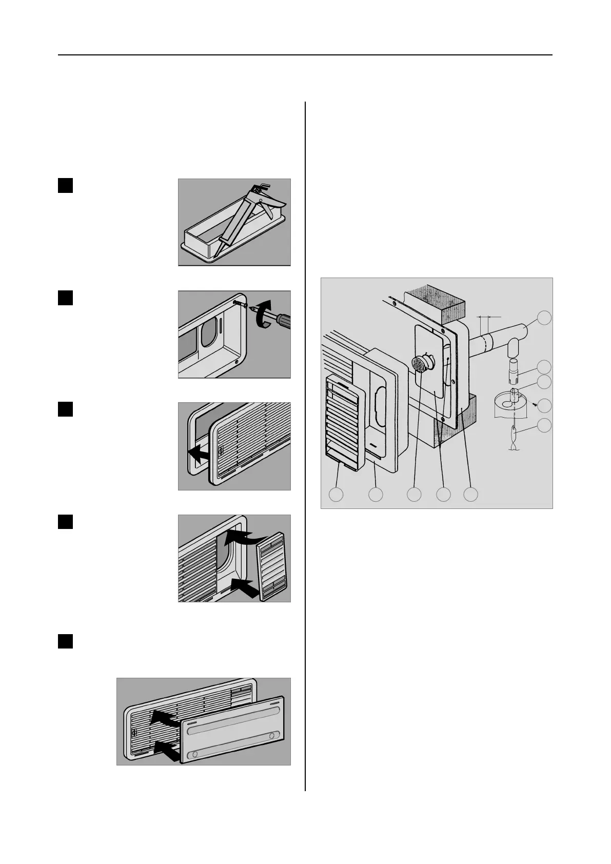
Fig. 20
Fig. 24
Seal the mounting frame
making it waterproof
(
does not apply for
mounting frames with
integral seal
).
1
Fig. 21
Insert frame and screw
into position
2
To install the ventilation grilles, cut two rectan-
gles (451 mm x 156 mm) in the outer wall of
the vehicle (
for position of the cuts, see point
4.2
).
Fig. 22
Insert and lock ventilati-
on grille.
3
Fig. 23
Clip the insert for flue
gas duct in position (
only
for L100 upper ventilati-
on system kit
).
4
Insert winter cover.
5
Installation
The exhaust gas duct system must be made in
such a manner as to achieve a complete
extraction of combustion products to the out-
side of living space. The duct system must
slope in an upward direction in order to avoid
a build-up of condensate. The type of exhaust
gas duct shown in Fig. 25 allows the installati-
on of the winter cover next to (10) (Fig. 25).
4.4 Exhaust gas duct and instal-
ling the fume flue
Installing the standard fume flue
1. Connect T-piece (1) to adaptor (2) or flue
pipe (3) as required and affix with screw (4).
Ensure that heat baffle (5) is lodged in the cor-
rect position.
2. Insert flue pipe with cover plate (6) through
the appropriate aperture in the upper frame (7)
and connect to T-piece (1). If necessary, shor-
ten flue pipe (6) to the required length.
3. Insert and lock ventilation grill LS 100 (8) in
the mounting frame (7).
4. Put cap (9) on flue pipe (6).
5. Insert extractor insert (10) into ventilation
grille (8) .
Fig. 25
1
2
3
4
5
6 79
10
8
min. 15mm
289 0318-00_EN_RMx8xxx-Installation_N1-1xx_Layout 1 24.04.2013 08:15 Seite 15
 Loading...