user’s manual TEC 30
7
GB
General information 1
INVERTER
CONTROL CARD
(C)
INTERNAL
CONTROL
PANEL
(D)
ALTERNATOR
UNIT
(B)
ENGINE (A)
EXTERNAL
CONTROL
PANEL
(F)
TERMINAL
BOARD (E)
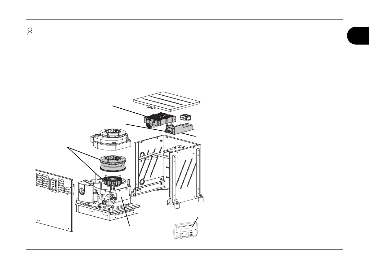
1.8 Operation description
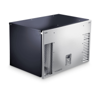
The main elements of the TEC 30 generator are: an engine (a), a permanent magnet alternator (b), an inverter (c), an internal control panel (d), a
terminal board (e) and an external control panel (f).
When the engine runs it drives the alternator to which it is solidly connected, which in turn generates alternating current that supplies the inverter.
The inverter “converts” the voltage supplied into a higher quality, perfectly stable voltage of 230 V and 50Hz supply.
The terminals, the socket where the extension of the external control panel is connected and the safety switch are located on the internal control
panel.
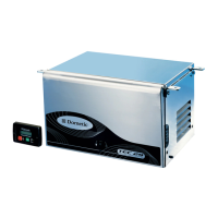
The external control panel is equipped with:
- buttons to start and stop the generator
- a back lit LCD screen showing the main electrical
properties, an indicator shows that the generator is
working properly and an hour counter is also displayed.
In the case of problem the alarm messages are dis-
played on this screen.
- LED indicators indicate low levels of petrol and oil.
 Loading...