15
Instruction Leaet IL01301051E
effective September 2013
Operating Manual for Series NRX
Trip Units - Digitrip™ 520/520M
EATON www.eaton.com
Section 3: Protection settings
General
Before placing any circuit breaker in operation, set each trip unit
protection setting to the values specified by the engineer responsible
for the installation. The number of settings that must be made is
determined by the type of protection supplied by each unit. Each
setting is made by turning a rotary switch. The selected setting for each
adjustment appears on the trip unit label. The installed rating plug will
establish the maximum continuous current rating of the circuit breaker
(I
n
). Instantaneous and ground current settings are defined in multiples
of (I
n
).
Should an automatic trip occur as a result of the current exceeding the
pre-selected value, the labeled LED will flash red.
ote:N Use the following to access Time Current Curves. Go to Eaton’s Web
site: http://www.eaton.com and search “NRX Digitrip 520 Curves”.
Long delay settings
The long delay current setting I
r
determines the maximum continous
current the circuit breaker can carry without tripping. Each setting is
expressed as a multiple of the maximum rated current I
n
set by the
rating plug. The nominal current pickup value is 110% of the setting.
The available current settings for the long time pickup I
r
are:
I
r
= (0.5/0.6/0.7/7.5/0.8/0.9/0.95/1.0) x I
n
ote:N I
r
is also the basis for the short delay current setting.
The long time delay t
r
determines the duration of an overload without
tripping. The available settings for the long time delay t
r
are:
t
r
= 2/4/7/10/12/15/20/24 s (at 6 x I
r
)
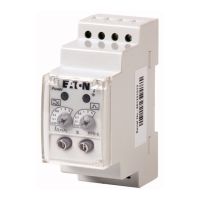
Figure 6.
Turn rotary
switch to change
long delay current
setting I
r
Turn rotary
switch to change
long delay time
setting t
Applying Long Delay Settings
Figure 7.
I
R
I
R
Available Settings
0.5, 0.6, 0.7, 0.75,
0.8, 0.9, 0.95, 1.0
In Multiples of
Amperes (I
n
)
Long Delay Current Settings
Figure 8.
t
R
Available Settings
2, 4, 7, 10, 12, 15,
20, 24 Seconds
at Six Times Long
Delay Setting (I
R
)
Long Delay Time Settings
ote:N In addition to the standard long delay protection element, trip units
also have a long time memory (LTM) function, which protects load circuits
from the effects of repeated overload conditions. If a circuit breaker is
reclosed soon after a long delay trip, and the current again exceeds the
long delay setting, (I
R
), the LTM automatically reduces the time to trip to
allow for the fact that the load circuit temperature is already higher than
normal because of the prior overload condition. Each time the overload
condition is repeated, the LTM causes the circuit breaker to trip in a
progressively shorter time. When the load current returns to normal, the
LTM begins to reset; after about 5 minutes it will have reset fully, so the
next long delay trip time will again correspond to the Setting value.
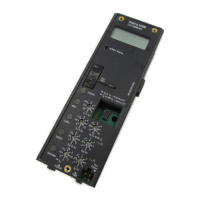
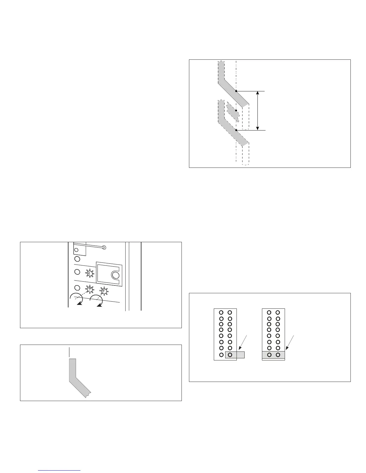
ote:N In certain applications, it may be desirable to disable the LTM
function. Open the test port cover with a small screwdriver blade by
prying up the edge near the test port marking. Use small, long-nose pliers
to move the LTM jumper inside the test port (see Figure 9) to its (pin
bridging) inactive position. (The LTM function can be enabled again at any
time by moving the LTM jumper back to its original Active position.)
The action of the LTM must be considered when performing multiple
long delay time tests (see Section 4).
Figure 9.
Test Kit Port
Test Port Test Port
Connector
(storage)
LTM
Active
Connector
(bridging)
LTM
Inactive
Position
for Field
Testing
Long Time Memory (LTM) Jumper
 Loading...