36
Operating Manual for Series NRX
Trip Units - Digitrip™ 520/520M
EATON www.eaton.com
Instruction Leaet IL01301051E
effective September 2013
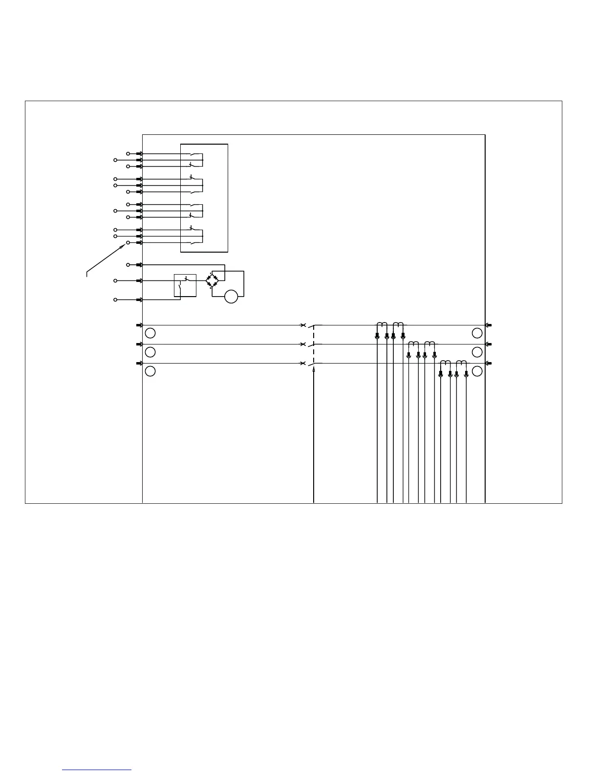
Figure 33.
PH1
A
PH2
B
PH3
C
4
3
2
1
4
3
2
1
4
3
2
1
CUTOFF
MOTOR
SWITCH
SC
EO1
EO2
+
MOTOR
OPERATOR
ELECTRIC
(OPTIONAL)
abbaab
4a 4b AUX. BOX TRAY
(LOCATED IN RIGHT POLE)
EO137
38 EO2
39 SC
a144
b145
c247
a350
b351
c453
43 c1
46 b2
48 a2
49 c3
52 b4
54 a4
246
135
M
SEE NOTE 8
Series NRX-NF frame (IZMX16/IZM91) breaker master connection diagram drawing number 6D32389 (continued from
previous page)
Notes for Figures 31 and 32 (Diagram drawing number 6D32389 - NF Frame)
1. All contacts shown with circuit breaker open and discharged and control power de-energized. The OTS are shown in reset position.
2. All trip unit wires are #22 AWG—0.34 mm
2
—300V.
3. All accessory wires are #18 AWG—0.82 mm
2
—600V.
4. 54 contacts maximum.
5. PT module inputs for Digitrip 1150 only.
6. Connectors K15 and K16 are not always present.
7. On three-pole circuit breakers only, connector K4—1.2 wires only are wired out to secondary contacts.
8. Odd number contacts have guide rib on black housing.
9. Zone interlock wiring shown dotted—optional jumper is standard.
10. Latch check switch can be wired either externally (option) or internally (option) to a spring release accessory. Wiring LCS internally
ensures the one-shot pulse provided by the SR circuitry is made active only after the mechanism spring is charged and the latch is
in its proper state.
11. For accessories having a DC rating, the odd numbers will be treated as positive voltage.
12. Reserved for spring charge SC input contact.
13. For Digitrip 520M ALM2 is an alarm used for GF (Ground fault style trip unit). ALM1 is used for diagnostic alarm or maintenance mode
active. For Digitrip 1150, these contracts can be programmed as desired.
 Loading...