4
Operating Manual for Series NRX
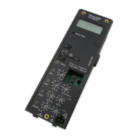
Trip Units - Digitrip™ 520/520M
EATON www.eaton.com
Instruction Leaet IL01301051E
effective September 2013
Contents
page
page
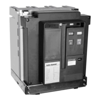
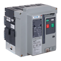
Section 1: General description of Digitrip trip units
in Eaton Series NRX circuit breakers ........................6
Sensors ............................................6
Digitrip Trip Unit ......................................6
Low-energy trip actuator ...............................6
Catalog Number Referencing ............................6
Protection ...........................................6
Mode of trip and status information ......................7
Installation and removal ...............................11
Trip unit/rating plug removal ............................11
Wiring .............................................11
Plexiglass cover .....................................11
Voltage supply input/alarms ............................11
Display feature (Digitrip 520M only) .....................12
Standards ..........................................12
Section 2: Principles of operation .........................12
Trip and operation indicators ...........................12
Making current release (MCR) ..........................12
High instantaneous ..................................13
Diagnostics indicator—circuit breaker/trip unit .............14
Ground Fault Protection ...............................14
Section 3: Protection settings ............................15
Long delay settings ..................................15
Short delay settings ..................................16
Instantaneous settings ................................16
Section 4: Test procedures ..............................21
When to test .......................................21
Functional field testing ................................21
Functional test kit (handheld) ...........................21
Test procedure ......................................21
Ground (Earth) Fault Performance Testing .................21
Section 5: Trip unit battery ...............................22
Battery check .......................................22
Battery installation and removal .........................22
Section 6: Rating plugs .................................23
Section 7: Maintenance Mode feature .....................25
Arcflash Reduction Maintenance System™ mode (ARMS) ....25
Maintenance Mode ..................................25
Maintenance Mode current setting ......................25
Actuating Maintenance Mode ..........................25
Remote indication of Maintenance Mode ................25
Tripping and testing ..................................25
Section 8: Communication Adapter
Modules (CAM) .......................................25
Section 9: References ..................................26
Time-current curves ..................................26
Curve Select ........................................26
Appendix A: Zone interlocking examples ...................27
Appendix B: Troubleshooting .............................27
Appendix C: Specifications ..............................28
Appendix D: Performance testing for ground fault trip units
primary injection ......................................31
Record keeping .....................................32
Appendix E: Typical breaker master connection diagram - NF ...35
Notes for previous page (Diagram drawing number
6D32389 - NF Frame .................................36
Appendix F: Typical breaker master connection diagram - RF ....37
Notes for pages 36 and 37 (Diagram drawing number
6D32424 - RF Frame) .................................39
 Loading...