64 Eaton 9355 UPS (10/15 kVA) User’s Guide 164201594—Rev H0
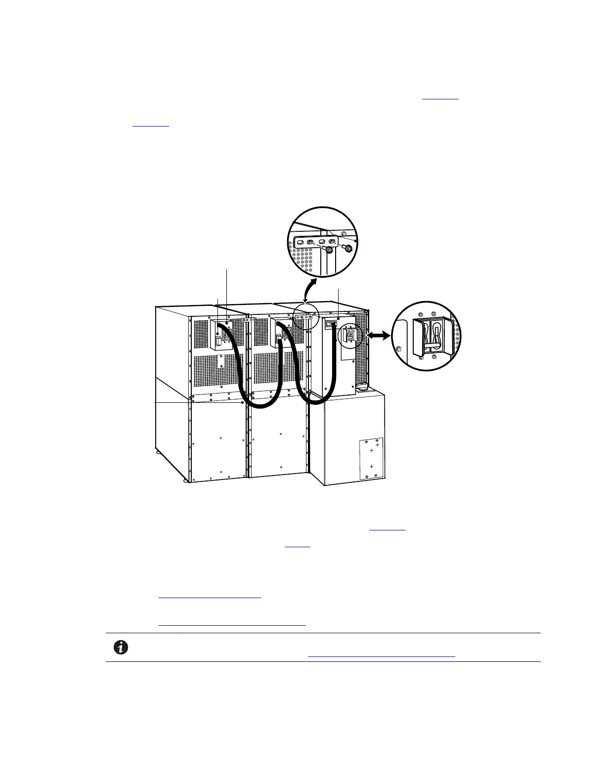
4. Install one ground strap between the UPS and EBM rear panels as shown in Figure 50.
5. If additional EBMs are installed, attach another ground strap between the first and second EBM as shown
in Figure 50. Repeat for each additional EBM.
6. Plug the EBM cable into the UPS battery connector.
7. If additional EBMs are installed, plug the EBM cable of the second cabinet into the battery connector on
the first EBM. Repeat for each additional EBM.
Figure 50. Typical EBM Installation (2-High Cabinets Shown)
UPS Battery Connector
Rear Ground Strap
EBM Battery
Circuit Breaker
EBM Battery Connector
EBM Cable
UPS Battery Circuit Breaker
8. Remove the top front covers of all cabinets.
9. Install the remaining ground straps between each cabinet (see Figure 51).
10. Reinstall the top front covers removed in Step 8.
Hang the top edge of the cover on the cabinet first, then lower the bottom edge and snap into place.
11. Continue to one of the following sections:
• See Chapter 6 Communication to install UPS communication options, such as X-Slot cards or remote
emergency power-off.
• See Chapter 7 UPS Operating Instructions to start up the UPS.
NOTE After UPS startup, ensure maximum battery runtime by configuring the UPS for the
correct number of EBMs (see Chapter 7 UPS Operating Instructions).
UPS System Installation
 Loading...


