-2-
★ The building wiring socket outlet (shockproof socket outlet) must
be easily accessible to close to the UPS.
★ With the installation of the equipment, the sum of the leakage
current of the UPS and the connected load does not exceed
3.5mA.
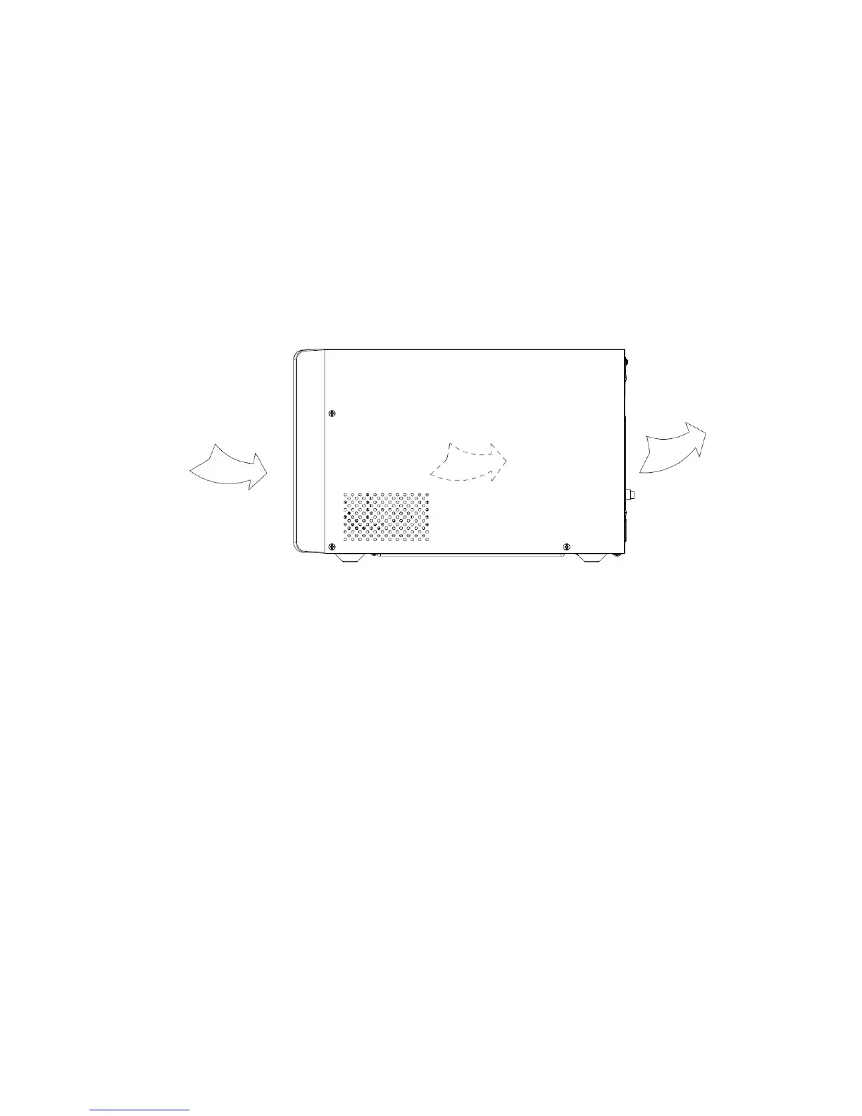
★ Do not block ventilation openings on the UPS’s housing. Ensure
the air vents on the front, side and rear of the UPS are not blocked.
Recommended at least 25cm of space on each side. The air flow
diagram is shown as below:
■ Figure 1.1 The Air Flow Diagram
★ UPS has provided earthed connector, in the final installed system
configuration, equipotential earth bonding to the external UPS
battery cabinets.
★ This UPS receives power from more than one
source-disconnection of AC source and the DC source is required
to de-energize this unit before servicing.
★ An additional circuit breaker or fuse with rating 32A and breaking
capacity 3kA shall be used between power source and input when
installation 3K/3K XL model.
★ An additional circuit breaker or fuse with rating 16A and breaking
capacity 3kA shall be used between power source and input when
installation 1K/1KXL/2K/2KXL model.
1.2 Operation
★ For safety consideration, do not disconnect the mains cable on the
 Loading...