Discrete inputs and outputs (auxiliary
I/O)
The CL-6 control provides the user with four discrete inputs
and four discrete outputs (Form C contacts); see Figures 7-6
and 7-7. The user can program the CL-6 control to use the
discrete input states, as well as other internal logic
conditions, to determine the operation of the control.
Likewise, the user can program the CL-6 control to toggle
the discrete output states based on internal control logic.
Note: If the CL-6 control is being applied in a CRA
application, the user may configure discrete inputs
#1 through #3. The fourth discrete input must be
reserved for use by the control.
EXAMPLE :
A utility noticed that the control function switch and
supervisory switch were being left in the incorrect positions
for their normal operation. The utility chose the User-
Defined LED to be the output of a PIO equation. They
used a standard equation with the logical OR operator.
Lastly, they chose inputs as the Supervisory Switch On
(Inverted) and the Control Status Switch Auto/Remote
(Inverted). Refer to Figure 7-5.
Supervisory On
Control Switch Auto/Remote
User LED On
OR
Figure 7-5. Logic diagram for the I/O example.
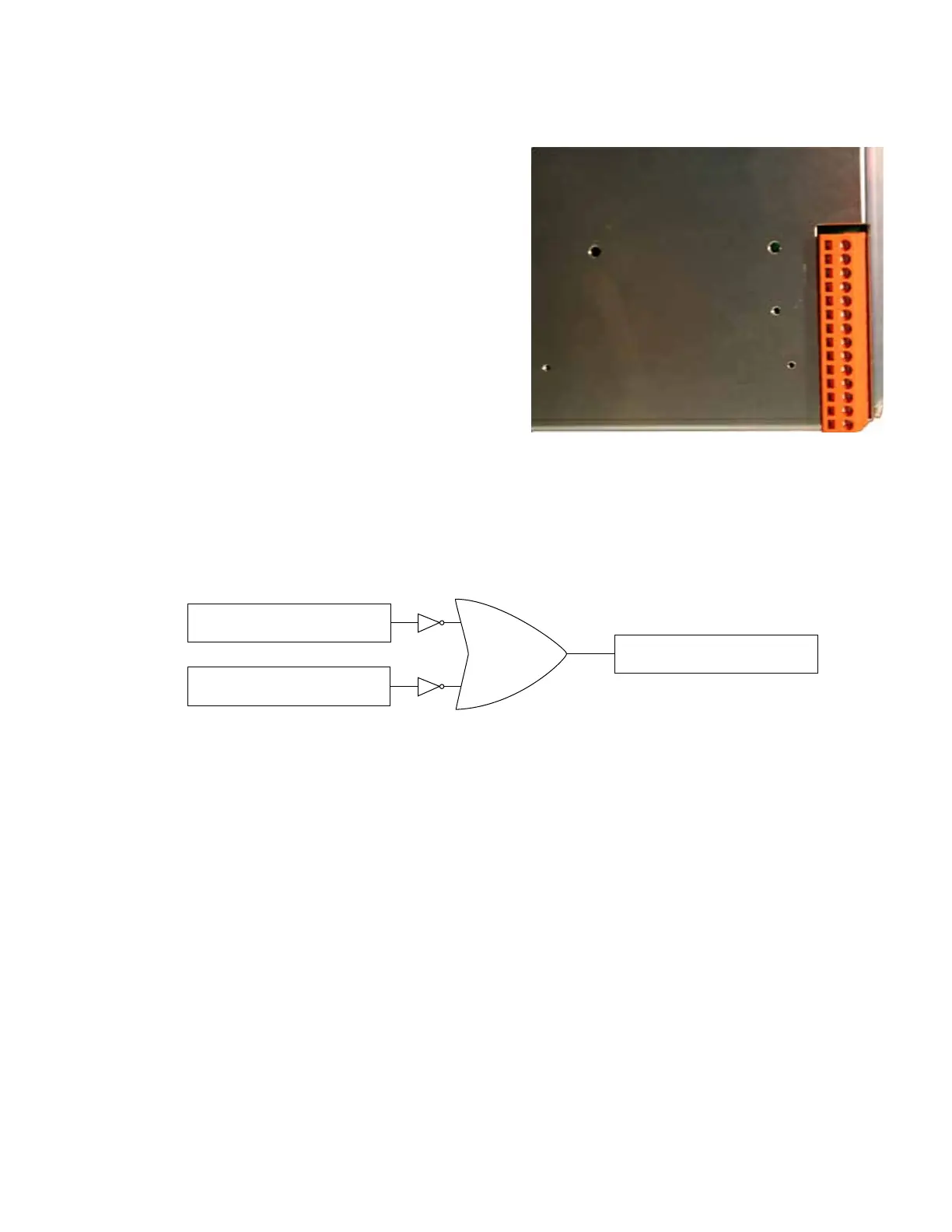
Figure 7-6. Discrete input and output connector.
97
CL-6 SERIES CONTROL INSTALLATION, OPERATION, AND MAINTENANCE INSTRUCTIONS MN225016EN January 2016
 Loading...


