I.B. ATS-V003
Page 15
Effective 6/98
With the enclosed transfer switch equipment unpacked
and ready for mounting, proceed with the following steps:
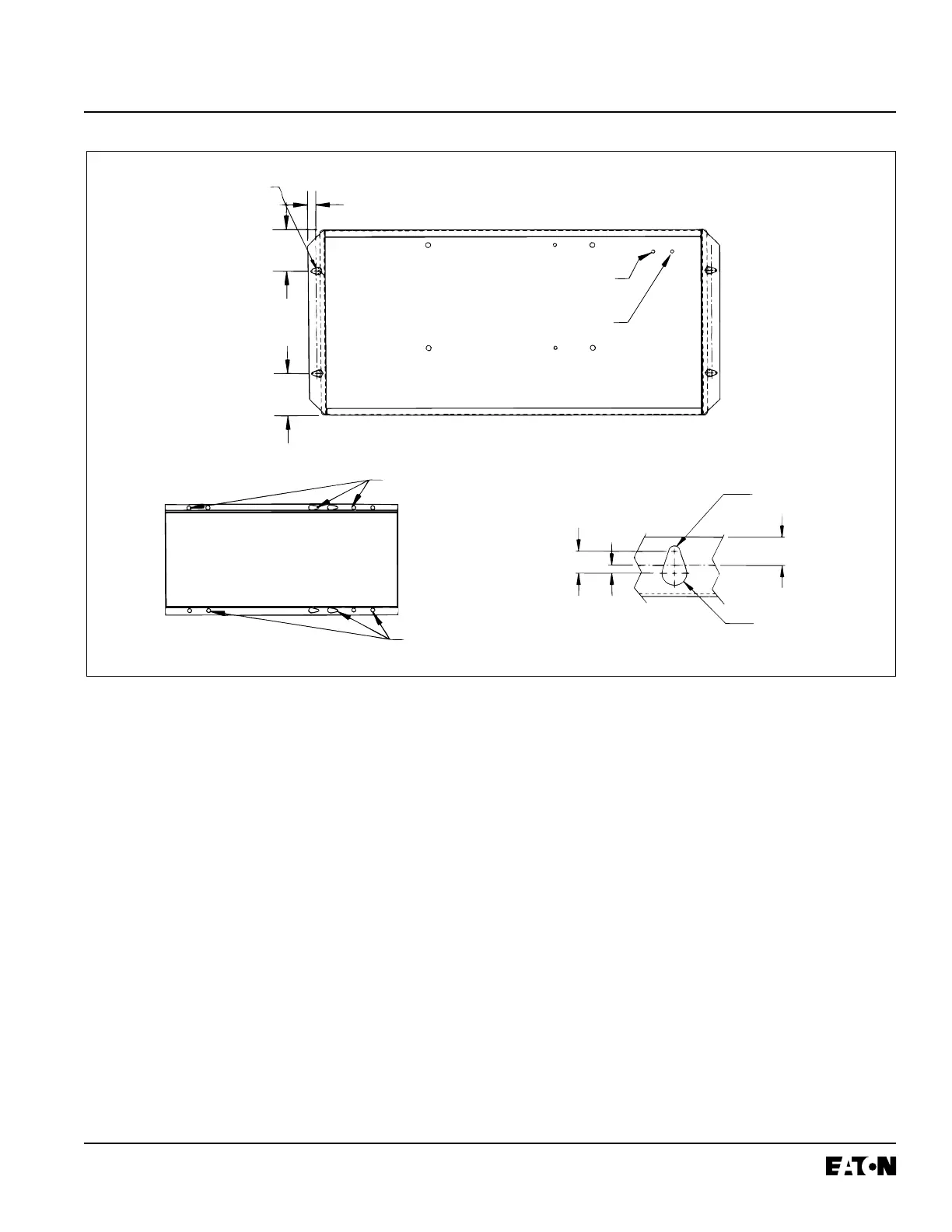
Step 1: The transfer switch enclosure door is hinge
mounted with removable hinge pins. To simplify
the mounting procedure and avoid damaging
the door mounted logic panel, carefully remove
the door and set aside in a safe place until
mounting is complete.
Step 2: Install required mounting bolt anchors and the
two upper mounting bolts in the mounting sur-
face.
Step 3: Gently lift the enclosure and guide the elongat-
ed holes in the upper mounting flange over the
upper mounting bolts, but do not completely
tighten the bolts.
Step 4: While still supporting the enclosure, install the
two lower mounting bolts in the lower mounting
flange, but do not completely tighten. Use
shims, if required, to prevent deformation of
the enclosure when the mounting surface is
distorted.
Step 5: Tighten all four mounting bolts after any
required shimming is completed.
Step 6: Double check to ensure that all packing and
shipping material has been removed.
4.4 VERTICAL DESIGN LOAD LUG LOCATION
Transfer switch equipment is supplied as standard from
the factory with its load terminal lugs at the top. If the

 Loading...