I.B. ATS-V003
Page 18
Effective 6/98
Step 8: Remount the operating mechanism to the front
of the power panel with the six bolts removed
previously in Step 4.
Step 9: Position the power panel in the enclosure such
that the two upper elongated holes, one on
either side of the power panel, fit over the two
positioning bolts located in the rear of the
enclosure. This will line up the four correct
mounting holes in the power panel with the
pre-tapped inserts in the rear of the enclosure.
Step 10: With the power panel held securely against the
back of the enclosure, replace and tighten the
four mounting bolts removed previously in Step 3.
Step 11: Attach the neutral strap to the back of the
enclosure through the upper bonding hole,
which may or may not have been previously
removed in Step 2
Step 12: Reconnect the connector plugs and the trans-
fer switch equipment is now configured for bot-
tom entry.
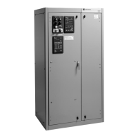
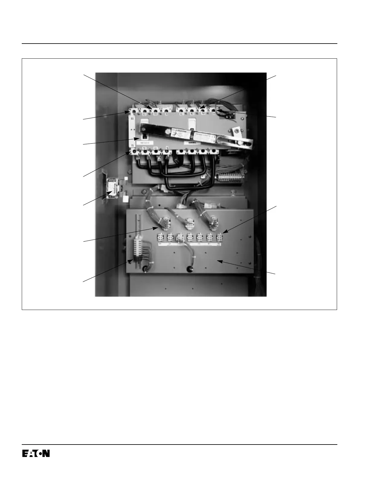
Figure 4-5 Typical (30-150 Amperes) Horizontal Design Transfer Switch Equipment (Door Open)
Normal Line
Connections
Transfer Mechanism
Voltage Selection
Connectors
Voltage
Selection Panel
Disconnect
Connectors
Emergency Line
Connections
Emergency
Power Source
Switching Device
Normal Power
Source Switching
Device
Load
Connections
Neutral
Assembly
Engine Start
Contacts
(Red Terminals)

 Loading...