I.B. ATS-V003
Page 17
Effective 6/98
Step 7: Turn the load lug assembly 180° with the lugs
at the bottom and remount the assembly by
reversing the procedures described in Steps 5
and 6. The mounting bracket will now be bolted
to the bottom of the power panel. Make certain
that all glass polyester phase barriers are in
place and positioned properly in the grooves
provided. When making any bolted connection
to the bus, comply with the torque require-
ments as outlined in Table 4.1.
Power Panel Torque
Switching Device in-lb (Nm)
Type FD 10 (13)
Type KD 20 (27)
Type LD 25 (33.8)
Type MA 25 (33.8)
Type ND/NB 25 (33.8)
Table 4.1 Bolted Bus Connection Torque Requirements
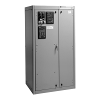
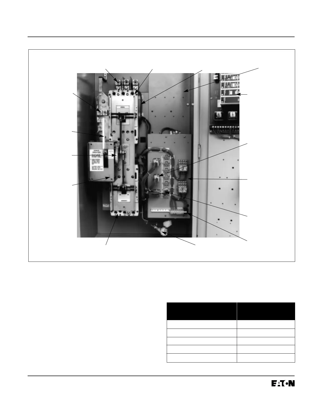
Figure 4-4 Typical (225-1000 Amperes) Vertical Design Transfer Switch Equipment (Door Open and Deadfront
Shield Removed)
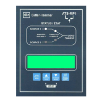
Door Mounted
Logic Panel
Motor
Disconnect
(S3)
Voltage
Selection
Panel
Voltage
Selection
Connectors
Neutral
Connections
Manual
Operating
Handle
Indicator
Wheel
Transfer
Mechanism
Load Lugs
(Top Entry)
Normal Power Source
Molded Case Switch
Power Panel
Emergency Power Source
Molded Case Switch
Door Disconnect
Plugs (Disconnected)
Transformer Panel
Engine Start
Contacts
(Red Terminals)

 Loading...