IB01602002E
Page 7
Effective 10/02
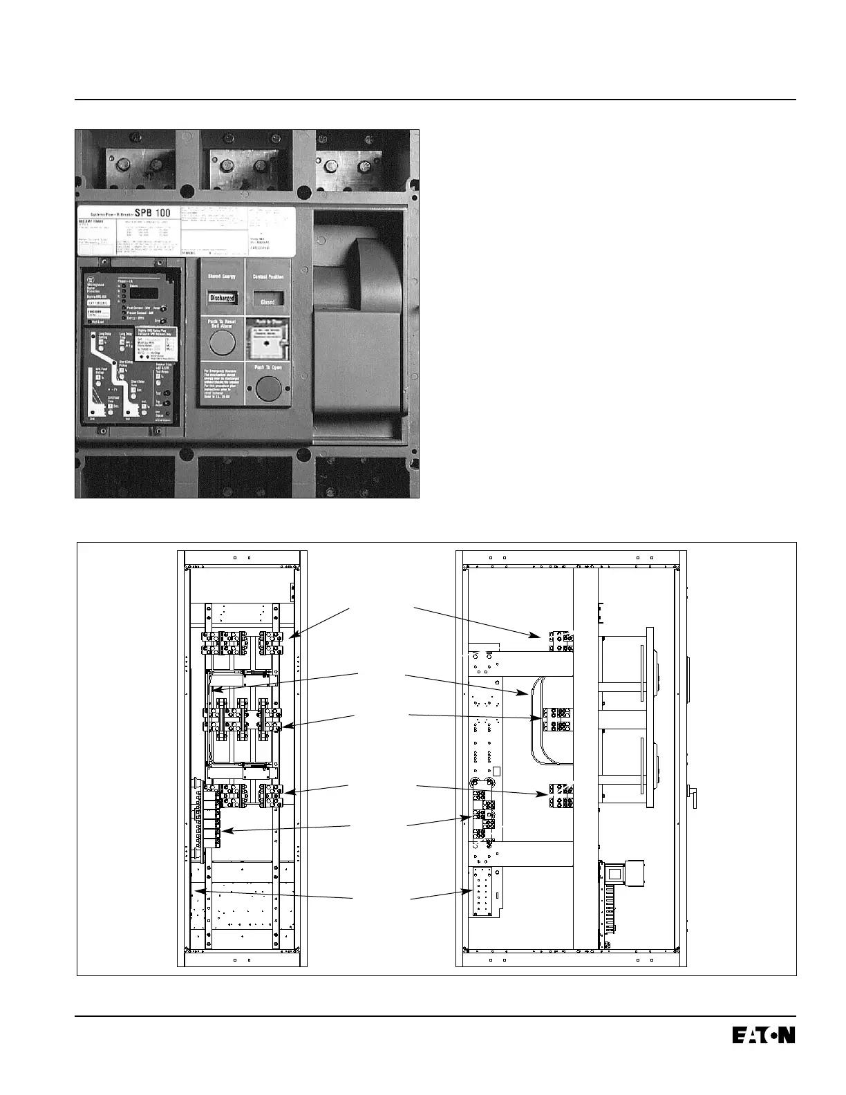
electrically interlocked to prevent the two sets of main
contacts from being closed simultaneously (Figure 3-4).
3.2.3 LOAD
The load side contacts of each switching device are
joined with a bus bar assembly to form a common load
terminal location (Figure 3-4).
3.2.4 TRANSFER MECHANISM
The transfer switch uses Cutler-Hammer SPB Type insu-
lated case circuit breakers and insulated case switches
with a stored-energy mechanism. An electrical operator
automatically recharges the mechanism after the switch-
ing device has been closed. An indicator on the switch
shows whether it is in the OPEN or CLOSED position
and the status of the stored-energy mechanism. (Figure
3-2).
Figure 3-3 Fixed Insulated Case Circuit Breaker
(closed transition shown)
Figure 3-4 Terminal Connections for Typical Fixed Mount Transfer Switch (1600-2000A open transition shown)
Normal
Connections
Interlock
Cables
Load
Connections
Emergency
Connections
Neutral
Connections
(solid neutral
shown)
Ground
Connections
(Rear View)
(Side View)
 Loading...