37OPERATION AND INSTALLATION INSTRUCTIONS MN280075EN July 2018
Form 6 microprocessor-based rack-mount recloser control
RS485 Serial communication card
The RS485 serial communication card accessory provides
means for establishing asynchronous link-based digital
communications with the Form 6 control. The Galvanic
isolated (1000V DC) RS485 port uses a single shielded
twisted pair connection and can support 32 devices in
multi-drop configuration. Communication speed is controlled
through software and can be set at: 1200, 2400, 4800,
9600, 19.2k, and 38.4k. Modbus can also be set at 57.6k.
Digital communications must be programmed through the
Communications Workbench to ensure proper operation of
the RS485 communication card accessory. Refer to Service
Information S280-70-4 (ProView 4.X.X) or S280-70-21
(ProView 5.X.X) Form 6 Control Programming Guide for
additional protocol support information.
Fiber-optic based serial communication card
The Fiber-Optic based Serial Communication Card offers
means of establishing asynchronous (RS-232 like) digital
communications through multi-mode fiber media. The use of
the fiber-optic based serial communication card accessory
can enhance communication reliability, and provides
excellent electrical isolation thus protecting transmitted data
from extraneous electrical interference.
An optional fiber-optic-to-RS-232D converter with DB-9
connector (Catalog Number KME6-1875-1) is available for
interfacing between an optical signal and a hard-wired
RS-232 signal, when required. This converter is compatible
with loop (ring) and point-to-point (star) configurations.
A pair of industry standard ST type fiber-optic connectors
are mounted on the back of the board enabling customer
connection to a digital communication system using
fiber-optic cables (customer-supplied).
The fiber-optic link has separate receive (RX) and transmit
(TX) ports operating at 820nm. Typical transmission distance
is 2000m with 62.5/125µm multi-mode fiber. Consult your
Eaton representative for availability of long haul solutions.
Link communication speed is controlled through software
and can be set at: 1200, 2400, 4800, 9600, 19.2k, and
38.4k. Modbus can also be set at 57.6k.
The fiber-optic accessory must be programmed through the
Communications Workbench for the appropriate protocol.
Refer to Service Information S280-70-4 (ProView 4.X.X) or
S280-70-21 (ProView 5.X.X) Form 6 Control Programming
Guide for additional information.
The fiber-optic based serial accessory includes TX and
RX indicating LEDs for verifying communications along
with an echo/non-echo switch for supporting ring/star
fibertopologies.
When operated in a ring configuration, the toggle switch
must be set in the ECHO position. In this mode, the
fiber-optic card will repeat (pass through) all messages
received on the RX fiber, and will respond to the Master
station by first echoing the incoming command and then
sending the response. This arrangement is best suited for
creation of low cost multi device fiber loops. For reliable
communications, the fiber loop system requires that all
devices in the loop remain powered at all times, thus
enabling unobstructed flow of information throughout
the loop.
A more resilient system can be designed by using the
fiber-optic ports in a point-to-point or multiple point-to-point
(star) configuration. For this mode, the toggle switch must
be set in the NON-ECHO mode. The Form 6 control will
respond to the Master station by sending a response only
(total separation of Receive and Transmit fibers). Additional
hardware (fiber-optic star coupler) is required to support the
multiple point-to-point device configurations.
Ethernet communication cards
The Ethernet communication card accessory brings the
Ethernet network connectivity to the Form 6 recloser control
platform. It is highly flexible, offering simultaneous support
for multiple sessions, device management (ProView over
TCP/IP) and SCADA communications (DNP3 over TCP/IP).
By natively supporting a set of widely accepted industry
standards (TCP/IP, UDP/IP, OSI) the Ethernet communication
accessory ensures seamless interoperability with other
network devices.
TX
RX
NON-ECHO
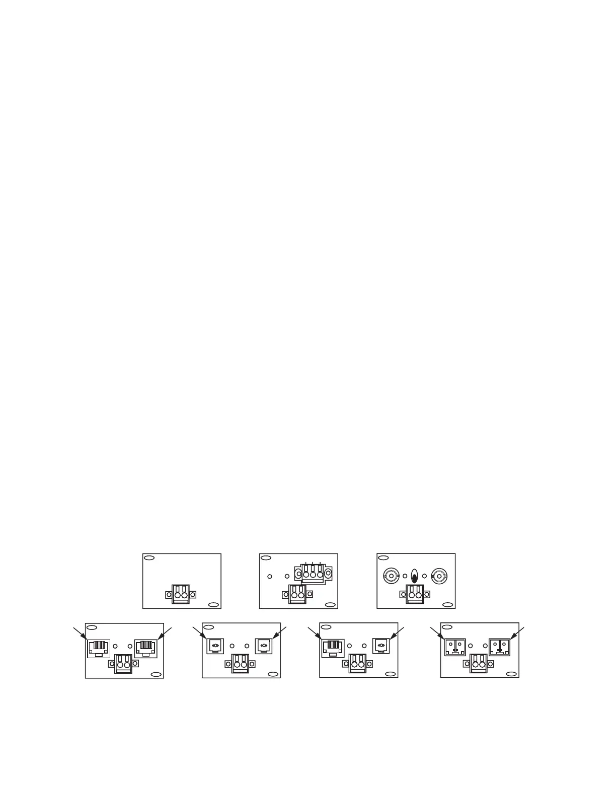
Serial Fiber
Ethernet 100 Base-FX
Type 2
Ethernet 10/100 Base-T,
100 Base-FX
Type 3
Ethernet 10/100 Base-T
Type 1
#2 #1
(No Communication Option)
IRIG-B
J5
RS-485 Communication
RS-485 C
-
+
RX
TX
#2
#1#2 #1
IRIG-B
J5
J4 – ETHERNET – J3
2 1
IRIG-B
J5
J4 – ETHERNET – J3
2 1
IRIG-B
J5
J4 – ETHERNET – J3
2 1
IRIG-B
J5
IRIG-B
J5
Ethernet 100 Base-FX
Type 4
Default
Primary
Ethernet
#2 #1
IRIG-B
J5
J4 – ETHERNET – J3
2 1
Figure32. Back panel ethernet and communication options
 Loading...