16 OPERATION AND INSTALLATION INSTRUCTIONS MN280075EN July 2018
Form 6 microprocessor-based rack-mount recloser control
Grounding Terminal Stud
.25 inch diameter x .75 inch length
TB1
1
2
3 57911 13 15 17 19
46 81012141618
CI1
CI2CI3 SS1 CO1
CO2 CO3
CO4
CI4
CI1CI2 CI3SS1 CO1 CO2 CO3CO4
TB3
1
3
579111315171921
CI5CI6 CI7CI8 CI9CI10CI11CO5 CO6
TB4
2
46 81012141618
20
CI4CI5 CI6CI7 CI8CI9 CI10 CI11 CO5
CO6
13
5
7911 13
CO7CO8
CO9CO10CO11
CO12
2
46 81012
CO7CO8 CO9CO10CO11CO12
FUSE
(10 AMP)
FUSE
(10 AMP)
TB5
+
1
-
5
2
-
4
+
INPUT POWER AUXILIARY POWER
28 VDC
RECLOSER INTERFACE CONNECTIONS
A
1
D
3
F
57
2
B
4
C
6
E
TB6
TB2
•
12
•
34
•
56
•
78
•
910
•
11 12
•
13 14
•
15 16
•
17 18
•
19
20
I(1-2)
I(3-4) I(5-6) V(1-2)
V(3-4) V(5-6) V1
I(SEF)
J1-RS-232
IRIG-B
RS-485
RS-232 DTE
C + –
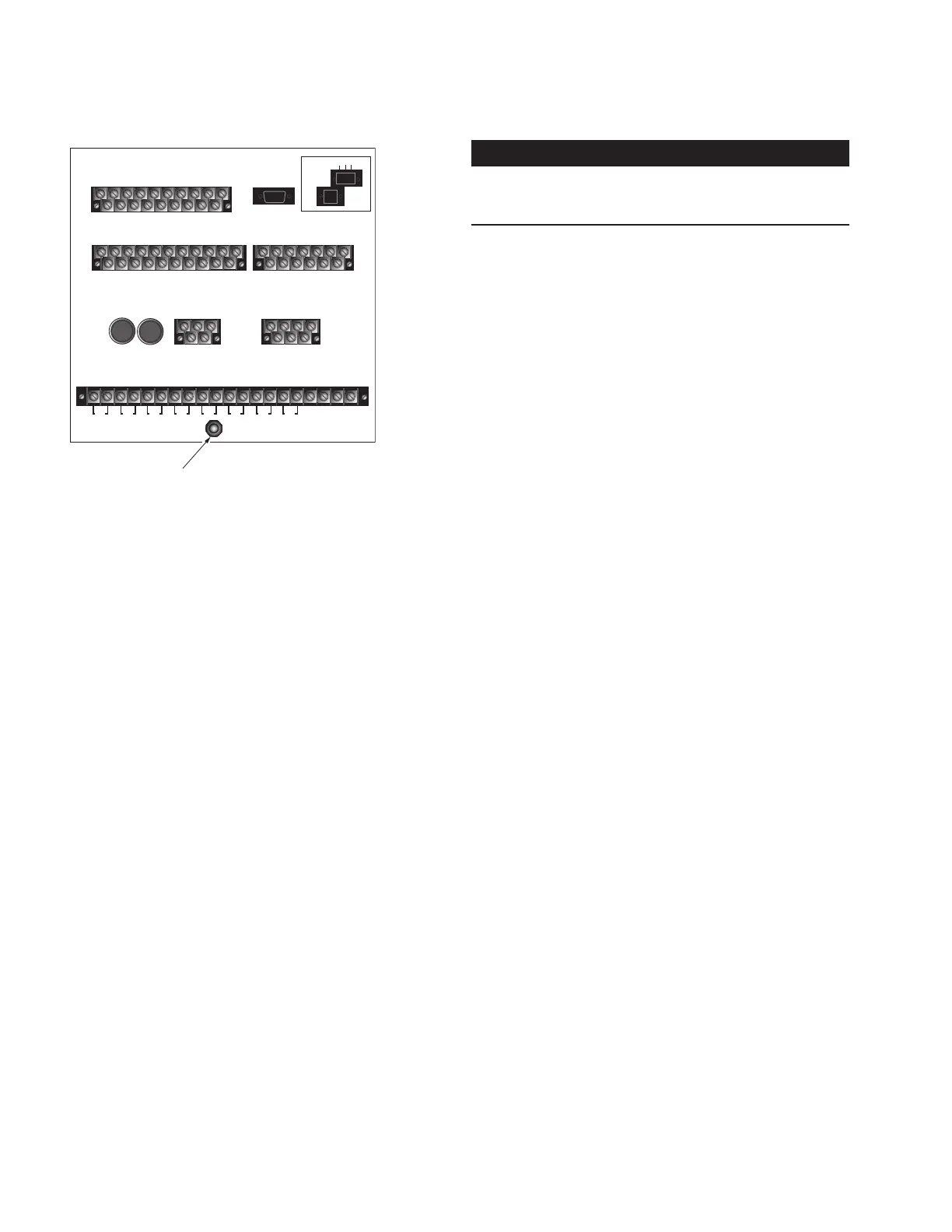
Figure10. Form 6 rack mount control grounding
terminal identification (back panel)
Customer connections for DC power and AC
voltage sensing
DC Power
Wiring connections to the Form 6 rack mount recloser
control are made to the back panel (Figure11). Input DC
power is required to power the control.
IMPORTANT
Verify the label on the Form 6 rack mount recloser control
matches the voltage of the substation supply prior to
installation.
DC power is connected to terminal block TB5, terminal
points 1(+) and 2(–). Battery negative is not grounded at the
control as the control should be grounded as discussed in
the Grounding the Control section.
AC Voltage sensing
Input AC power is required to provide the
followingfunctions:
Directional Protection
Sync Check Protection
Voltage Protection
Frequency Protection
Single- or Three-Phase Voltage and Power Metering
AC voltage input connections are connected to TB2 for Wye
connections only. Figure11 illustrates three-phase wiring
connections for source side connections and single-phase
wiring connections for load side connections.
ote:N Three-phase wiring connections for load side
connections are not available.
Figure12 illustrates customer connections to TB2, 120 VAC
Delta connection.
 Loading...