39OPERATION AND INSTALLATION INSTRUCTIONS MN280075EN July 2018
Form 6 microprocessor-based rack-mount recloser control
All other tests described in this TESTING section require
the Form 6 recloser control to be removed from service,
connected to a bypassed recloser, or tested at a location
where the proper testing equipment is available. Refer to
Remove the control from service for the proper procedure
to remove the control from service.
CONTROL POWER
CONTROL OK
CONTROL LOCKOUT
RECLOSER OPEN
RECLOSER CLOSED
A PHASE FAULT
B PHASE FAULT
C PHASE FAULT
GROUND FAULT
SENSITIVE GND
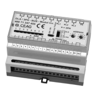
Control OK LED
Figure34. Control OK LED
Remove the control from service
IMPORTANT
Disconnect switches for both AC and DC circuits and
a current transformer shorting-type terminal block are
necessary to isolate the Form 6 recloser control for testing
and servicing.
1. Enable GND TRIP BLOCKED to allow for ground trip to
be disabled when re-energized.
A. Press the CHANGE button on the Operator Panel
to enter the CHANGE mode.
B. Depress the GND TRIP BLOCKED button within
ten seconds after entering the CHANGE mode.
ote:N If the GND TRIP BLOCK button is not depressed
within ten seconds, the function is not activated.
2. Remove DC power from the control using a separate
disconnect switch.
3. Remove control AC sensing voltage from the control
using a separate disconnect switch.
CAUTION
Hazardous voltage. Open CT secondaries can generate
high voltages. Contact with CT pins of the disconnected
cable can cause electric shock and may result in personal
injury. Open recloser contacts and open disconnect
switches before disconnecting control cable. T204.3
4. Short CT secondaries at a separate CT shorting-type
terminal block.
5. Remove any control input and status output wiring from
TB1, TB3, and TB4 (Figure7).
6. Disconnect any serial communications ports and IRIG-B
timing connection (Figure7).
7. Unscrew the mounting screw on each side of terminal
block TB5 (Input Power) to disconnect and remove the
terminal block from the control.
NOTICE
Equipment damage. Pin 1 retains a 24 VDC charge.
Never allow conductive material (such as a screwdriver
or other metal item) to touch TB6 Pin 1 to chassis.
Failure to comply will damage the control. T272.0
8. Unscrew the mounting screw on each side of
terminal block TB6 (Recloser Interface Connections)
to disconnect and remove the terminal block from the
control (Figure7).
9. Use a screwdriver to disconnect all wiring on terminal
block TB2 (Voltage/Current Inputs) from the control
(Figure7).
10. Disconnect the ground from the control.
11. Carefully transport the control to a suitable
servicefacility.
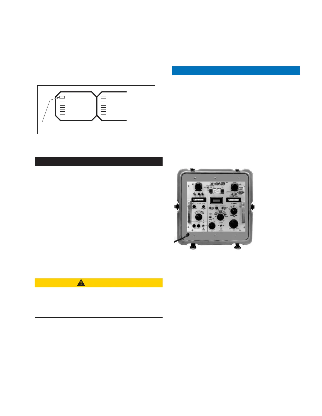
Figure35. Eaton’s Cooper Power series type MET
electronic recloser control tester
Testing with type MET tester
The Eaton Cooper Power series Type MET Electronic
Recloser Control Tester (Figure35) is used for testing the
following functions of the Form 6 recloser control:
Overcurrent Timing
Reclose Time
Operating Sequence
Reset Time
Minimum Trip Current
High Current Trip and Lockout
The MET Tester is completely self-contained, capable of
performing all required checks and tests from a simple
verification of operation to a complete verification of
all operating parameters. Refer to Service Information
 Loading...