CL-7 control in General Electric control box
with pin-type terminal
Table 6. Kit parts identification
Item Description Part Number Qty
1 CL-6B PRA wiring harness,
General Electric, pin-type
A64316200H 1
2 Hinge bracket assembly E0003X00G22 1
3 Left side bracket E0003X00G25 1
4 Self adjusting latch E0003X00G158 1
Required tools
Screwdriver (Phillips head)
3/8-Inch nut driver or combination wrench
ote:N Verify all kit items are present before beginning
installation procedure.
Installation procedure
Follow these instructions to install the CL-7 PRA on a
voltage regulator manufactured by General Electric with
pin-type terminal connections.
1. Remove existing control per manufacturer‘s
requirements. Retain the hinge pins.
2. Remove the circuit board from the control box
back panel by pressing the white plastic levers out
and sliding it down. Disconnect the existing wiring
harness from the circuit board and save the board for
reinstallation.
ote:N If the General Electric pin-terminal wiring harness
(Figure 34), hinge bracket and latch bracket
(Figure 36) have already been installed on the new
CL-7 control, proceed to Step 12.
ote:N The GE harness may be equipped with two wires
colored white and white/blue with two-terminal
connectors as shown in Figure 34. The wires are for
connection to the CL-7 control general purpose inputs
(GPIs). The wires can be used for analog voltage
reduction or other programmable functionality. See
document MN225003EN, CL-7 Voltage Regulator
Control Installation, Operation, and Maintenance
Instructions for more information on the GPIs.
Figure 34. Item 1, the General Electric pin-terminal
wiring harness for the CL-7 control
3. Using a screwdriver, remove the four screws to
uninstall the existing latch bracket from the left side of
the CL-7 control; retain the screws. See Figure 35.
Figure 35. Removal of latch bracket from CL-7 control
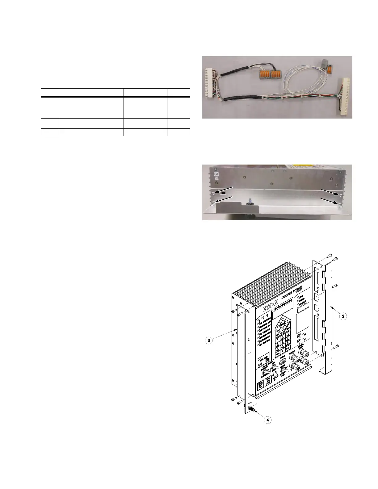
4. Install the General Electric latch bracket (Item3) using
the screws retained from the last step. See Figure 36.
3
2
4
Figure 36. Installing hinge and bracket assemblies
13
CL-7 Control Panel Retrofit
InstallatIon InstructIons MN225018EN April 2018

 Loading...


