CL-7 control in Eaton control box, not dead
front
Table 2. Kit parts identification
Item Description Part Number Qty
1 Wiring harness assembly,
Fanning strip style
A64316200E 1
2 18-position terminal board kit A64289100B 1
3 Terminal jumper TAA114731001 2
4 Jumper wire 102A008HEHE043 1
ote:N Eaton‘s Universal PRA kit may include parts not
required for every installation. Only parts required for
this installation are included in this list.
Required tools
Screwdriver (Standard)
Screwdriver (Phillips)
ote:N Verify all kit items are present before beginning
installation procedure.
Installation procedure
Follow these instructions to install the CL-7 PRA into a
control box on an Eaton voltage regulator with a fanning
strip terminal board connection.
1. Remove the existing control. Refer to the appropriate
voltage regulator control manual for complete
instructions on removing a control.
For example, refer to Service Information S225-10-10,
McGraw-Edison® VR-32 Regulator and CL-5 Series
Control Installation, Operation and Maintenance
Instructions for information on the CL-5 series voltage
regulator control.
2. If the control box contains a 10-position TB1 terminal
board (see Figure 8), it must be upgraded to an
18-position board. See document MN225019EN,
Back Panel Upgrade 10- to 18-Position Terminal Strip
Installation Instructions for instruction on installing the
18-position terminal board.
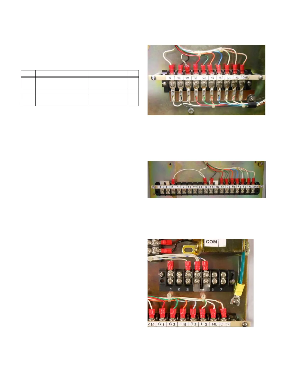
Figure 8. Obsolete 10-position terminal board to be
replaced
3. If the control box is already equipped with the
18-position terminal board, it must be reconfigured to
the correct jumper configuration. A metal jumper is
required between terminal 3 and 4 and a wire jumper is
required between terminals 2 and G (see Figure 9).
Figure 9. Proper jumper arrangement on 18-position
terminal board for the CL-7 voltage regulator control
4. If a jumper is present between terminals 4 and 5 of
TB8 (see Figure 10), remove the jumper. If this jumper
remains in place, the CL-7 control will display an Auto
Tap Blocked indication.
Figure 10. Remove metal jumper between terminals 4
and 5
4
CL-7 Control Panel Retrofit
InstallatIon InstructIons MN225018EN April 2018

 Loading...


