5. On some older units, a wire connection between
the VM terminal and terminal 127 on an RCT may
be present. In these cases, it is best to remove the
connection and reconnect the VM and VS terminals
with a metal jumper as shown in Figure 9.
NOTICE
If the jumper between VS and VM is in place and the
connection to the RCT terminal 127 is not removed,
wire damage will occur.
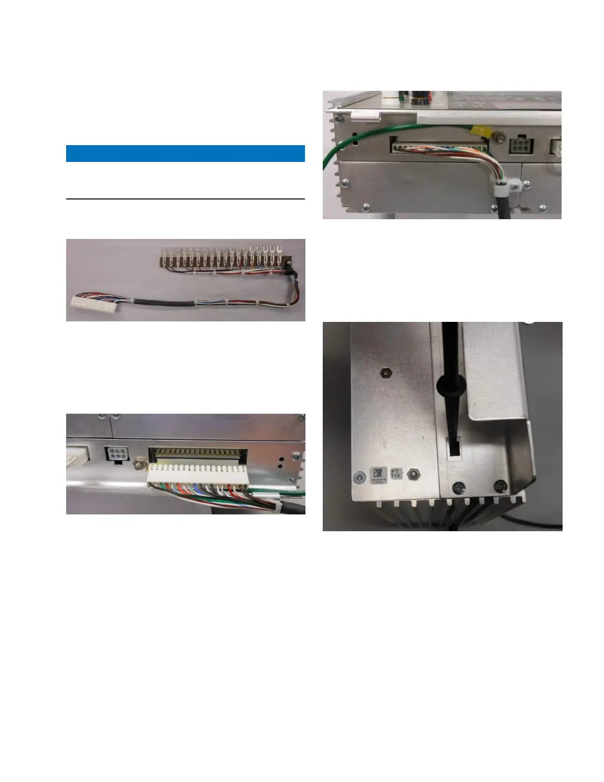
ote:N If the fanning strip style wiring harness (Figure 11)
has already been installed on the control, proceed to
Step 9.
Figure 11. Item 1, Eaton fanning strip wiring harness for
the CL-7 control
6. Remove the strain relief screw (retain the strain relief
device) and disconnect the white connector from the
side of the CL-7 control panel. See Figure 12. Reinstall
the screw that had been holding the strain relief device
in place.
Figure 12. Removal of standard wiring harness
7. Install the new wiring harness assembly (Item1) in the
connector located on the side of the CL-7 control panel.
Refer to Figure 13.
8. Remove a screw and install the strain relief device
under the screw as shown in Figure 13.
Figure 13. Wiring harness installed with repositioned
strain relief device
9. If the new control is being installed on an Eaton/
McGraw-Edison voltage regulator built in 1988 or
earlier, the neutral light configuration switch must be
set. Locate the switch on the left side of the control
near the bottom. Using a small screw driver, flip the
switch down. See Figure 14.
Figure 14. Setting neutral light configuration switch
10. Slide the CL-7 control panel onto the existing hinge
pins.
11. Connect the green ground lead to the ground
connection located on the back panel of the control
encloser. Refer to Figure 15.
12. Install the wiring harness fanning strip into TB2 on the
backpanel. Refer to Figure 15.
5
CL-7 Control Panel Retrofit
InstallatIon InstructIons MN225018EN April 2018

 Loading...


