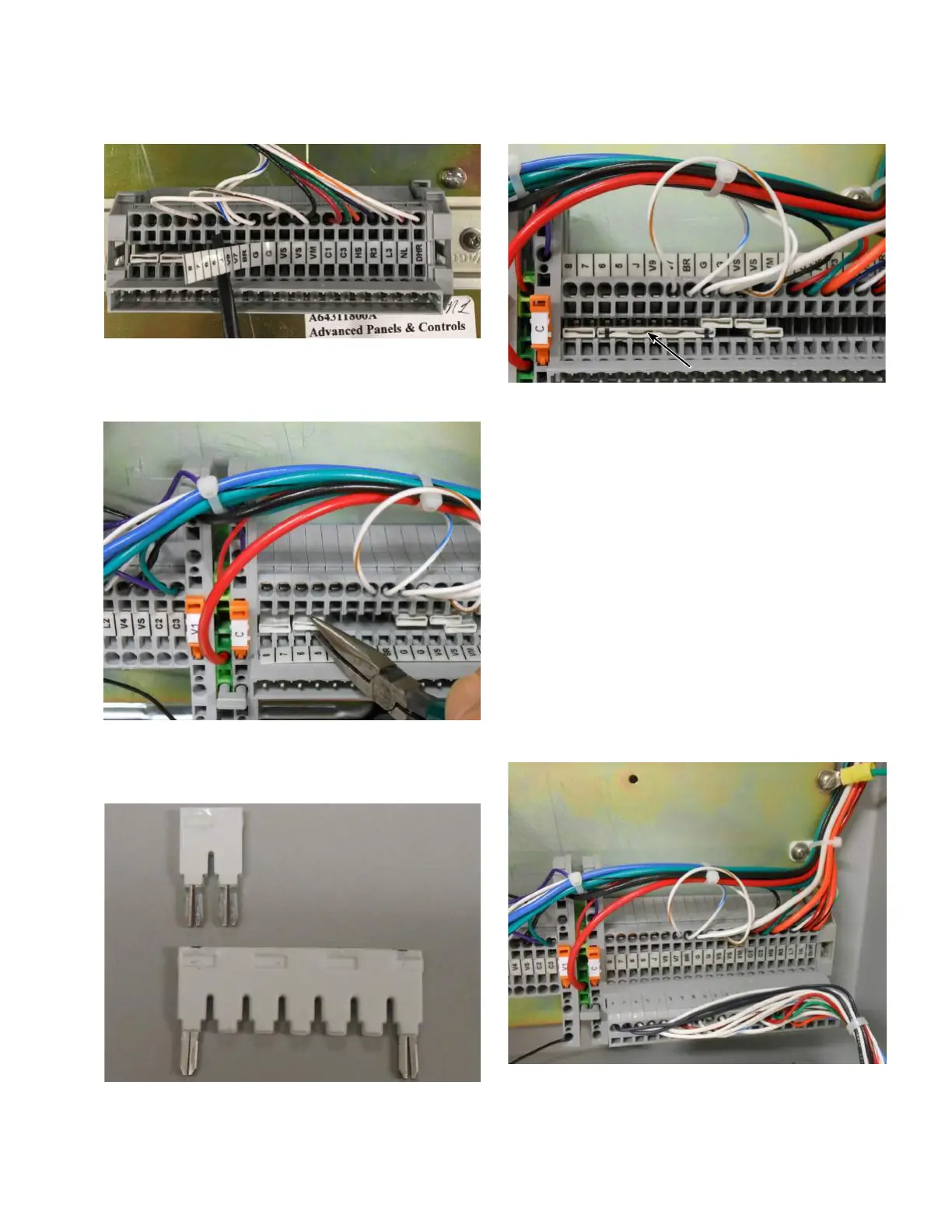
Figure 3. Revealing terminal board jumpers
5. Remove the jumper between terminals 5 and 6, if
present. Refer to Figure 4.
Figure 4. Removing jumper between terminals 5 and 6
6. If not present, install the 7-position jumper between
terminal 6 and G. Refer to Figure 5 and Figure 6.
Figure 5. Old and new jumpers
Figure 6. New jumper installed between terminals 6
and G
7. Reinstall the terminal marking strip over the jumpers.
8. Slide the CL-7 control panel onto the existing hinge
pins.
9. Connect the green ground cable to the back panel.
Refer to Figure 7.
10. Plug the wiring harness connector into terminal board
receptacle on the backpanel. Make sure to face the
plug in the correct direction so that the terminal
marking match those on the top of the plug. Refer to
Figure 7.
11. Secure the CL-7 control panel to the latch tab using the
latching screw.
12. Complete the control programming and testing as
required. Refer to document MN225003EN, CL-7
Control Installation, Operation, and Maintenance
Instructions for proper control configuration and start
up procedures.
Figure 7. Control plugged into backpanel terminal board
and ground wire connected
3
CL-7 Control Panel Retrofit
InstallatIon InstructIons MN225018EN April 2018

 Loading...


