10
EATON CORPORATION www.eaton.com
Instructions for Undervoltage Release, Shunt Trip, and Overcurrent
Trip Switch
Instructional Leaflet IL0131087EN
Effective January 2019
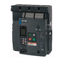
Figure 33. Step 3 (RF Frame Shown).
Step 4: With the left accessory tray positioned as shown, pull back
on the locking tab of each OTS switch to unlock them from the left
accessory tray.
Figure 34. Step 4 (NF Frame Shown).
Figure 35. Step 4 (RF Frame Shown).
Step 5: Remove both OTS switches by lifting them upward and out of
the tray.
Step 6: If the tray will have a new two OTS switch combination
installed, follow Steps 2 through 7 of Section 4. If not, just complete
Steps 4 through 7 of Section 4.
Section 6: Accessory Secondary Connections
CAUTION
BECOME FAMILIAR WITH THIS CAUTION ON POLARITY BEFORE
PROCEEDING. FAILURE TO APPLY THE CORRECT POLARITY WILL RESULT IN
DAMAGE TO THE DEVICE.
When connecting a 24 Vdc shunt trip or a 24 Vdc undervoltage release,
be certain to apply positive (+) voltage to either secondary terminal
1 (ST) or secondary terminal 3 (UVR).
General Information
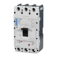
1 Electrical accessory leads are tagged with numbers associated with
the applicable connection diagram located in technical document
TD013001EN. Leads are also supplied with keyed secondary
connector plugs to ensure proper connections (Figure 36).
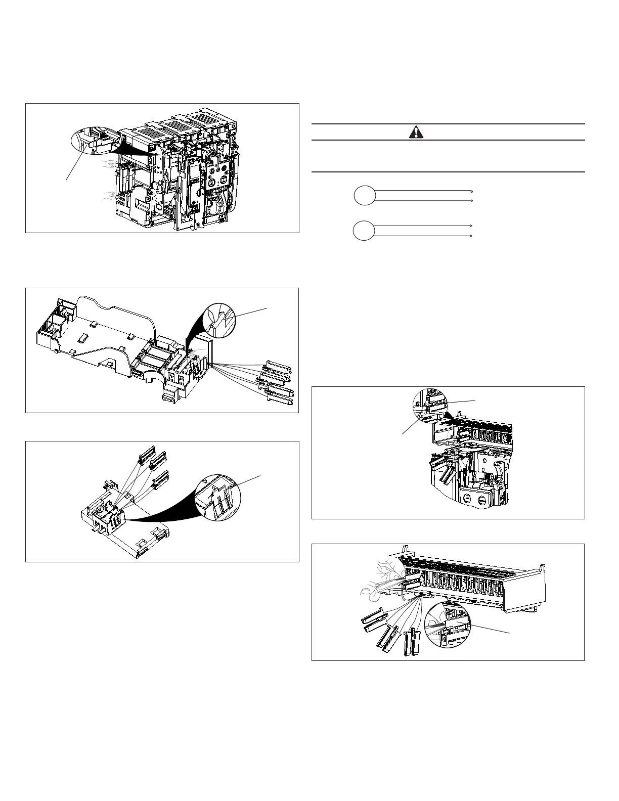
2 Secondary connections are made by plugging the connector plugs
into the appropriate location. A connector plug already connected
can be removed by squeezing two release tabs together with small
needle nose pliers and pulling out (Figure 37).
Figure 36. Leads and Connectors.
Figure 37. Connector Plug Removal.
Fixed Breaker Connections
Proceed with the following five steps:
Step 1: Become familiar with the fixed terminal block DIN rail type
mounting plate where secondary connections are made.
ote:N Secondary connection points have numerical and descriptive laser-etched
identifications.
3
4
DC Pos. (+)
DC Neg. (–)
UVR
2
DC Pos. (+)
DC Neg. (–)
ST
Thumb Tab
Accessory
Locking
Tabs
Accessory Locking
Tabs
Tagged Leads
Keyed Connector
Release Tab
 Loading...