2
EATON CORPORATION www.eaton.com
Instructions for Undervoltage Release, Shunt Trip, and Overcurrent
Trip Switch
Instructional Leaflet IL0131087EN
Effective January 2019
Section 1: General Information
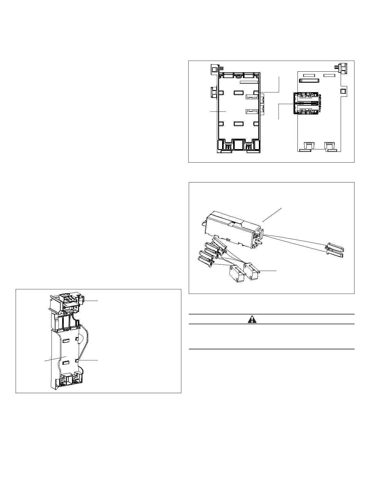
The left accessory tray will accommodate a maximum of four
accessory devices as follows (see Figure 1):
• Zero or two (OTS);
• Zero or one (UVR);
• Zero, one, or two (ST); and
• Combination (one ST and one UVR).
Shunt Trip (ST)
The shunt trip opens the circuit breaker when its coil is energized
by a voltage input (see Table 1). It is supplied with yellow and white
secondary leads connected to a secondary connector plug
(see Figure 2).
Undervoltage Release (UVR)
The undervoltage release opens the circuit breaker when its supply
voltage falls to between 35 - 60% of rated voltage. If the release is not
energized to 85% of its supply voltage, the circuit breaker cannot be
closed electrically or manually (see Table 2). It is supplied with orange
and brown secondary leads connected to a secondary connector plug
(see Figure 3). A UVR should only be installed in the right side of the
tray.
Overcurrent Trip Switch (OTS)
An overcurrent trip switch (bell alarm) provides an electrical indication
when a circuit breaker trips as a result of the trip unit reacting to an
overcurrent condition. An electrical indication will not occur unless a
standard or interlocking Trip Indicator is installed (refer to IL01301058E).
Opening as a result of a circuit breaker’s manual open button, ST
or UVR does not cause the overcurrent trip switch to operate (see
Table 3). OTSs are always supplied as a two-switch combination. The
combination is supplied with red, blue, and black secondary leads
connected to three secondary connector plugs (Figure 3).
ote:N A number of graphics in this instruction leaflet use the NF Frame breaker
only as typical examples. The RF Frame is similar in those situations.
Figure 1. Unpopulated Left Accessory Tray (NF Frame Shown).
Figure 2. Unpopulated Left Accessory Tray (RF Frame Shown).
Figure 3. Left Tray Accessories.
CAUTION
ANY SPECIFIC ACCESSORY LEAD ROUTING INSTRUCTIONS PRESENTED
IN THIS DOCUMENT SHOULD BE CAREFULLY ADHERED TO AT ALL TIMES.
FAILURE TO DO SO COULD RESULT IN LEAD DAMAGE AND/OR NO/
INAPPROPRIATE TRIPPING.
OTS Mounting Location
UVR Mounting Location
or Second ST
Shunt Trip and Undervoltage
Release with Secondary Connector
Two OTS Combination with
Secondary Connectors
OTS
Mounting
Location
Mounting
Location
Front Side Back Side
ST Mounting
Location
UVR or Second
ST Mounting
Location
 Loading...