9
EATON CORPORATION www.eaton.com
Instructions for Undervoltage Release, Shunt Trip, and Overcurrent
Trip Switch
Instructional Leaflet IL0131087EN
Effective January 2019
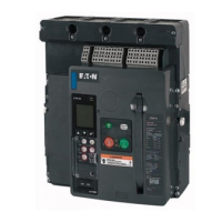
Figure 29. Step 4 (RF Frame Shown).
ote:N The Proper routing of leads will prevent the wires from being pinched by
the trip unit interlock plate in the RF Frame breaker.
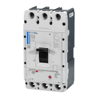
Step 5: The installed left accessory tray should look as shown in
Figure 30 with secondary leads extending out behind the trip unit
mounting plate location. Secondary connections can now be made.
Figure 30. Step 5 (NF Frame Shown).
Step 6: Make the appropriate secondary connections as outlined
in Section 6. If necessary, bundle secondary wires using industry-
accepted wire tie practices.
Step 7: Replace the front cover and secure it in place with the four
mounting screws previously removed in Step 1.
Section 5: Removal of Overcurrent Trip from
Left Accessory Tray
Proceed with the following six steps:
Step 1: If necessary, remove the front cover from the breaker by first
performing Steps 1 and 2 of Section 2.
Step 2: Locate the left accessory tray behind the trip unit and
disconnect the appropriate secondary connections as described in
Section 6.
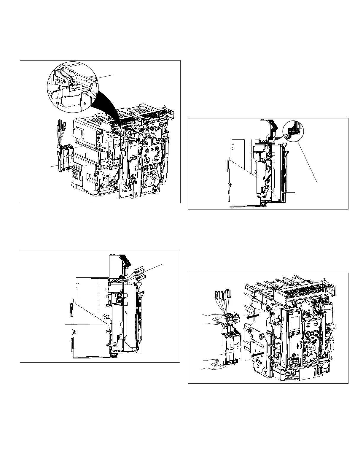
Figure 31. Step 2 (NF Frame Shown).
Step 3: Once the secondary leads are disconnected, finger depress
the tabs on each end of the NF Frame tray and slide it to the left as
shown for removal. For the RF Frame tray, press the thumb tab down
and slide the tray to the left for removal.
ote:N A minimum of 2 inches (50.8 mm) for NF Frame and 3 inches (77 mm)
for RF Frame of side clearance is required on an installed fixed breaker for tray
removal.
Figure 32. Step 3 (NF Frame Shown).
Accessory Tray
Installed
Secondary
Connectors
Connected Secondary
Connectors
Trip Unit Interlock Plate
ST
UVR
ST
UVR
 Loading...