7
EATON CORPORATION www.eaton.com
Instructions for Undervoltage Release, Shunt Trip, and Overcurrent
Trip Switch
Instructional Leaflet IL0131087EN
Effective January 2019
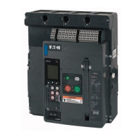
Figure 21. Step 3 (RF Frame Shown).
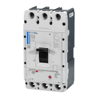
Step 4: Position the tray as shown and remove secondary leads
from behind molded retaining tabs of the accessory being removed.
Pull back on the locking tab to unlock the UVR or ST from the left
accessory tray.
Figure 22. Step 4 (NF Frame Shown).
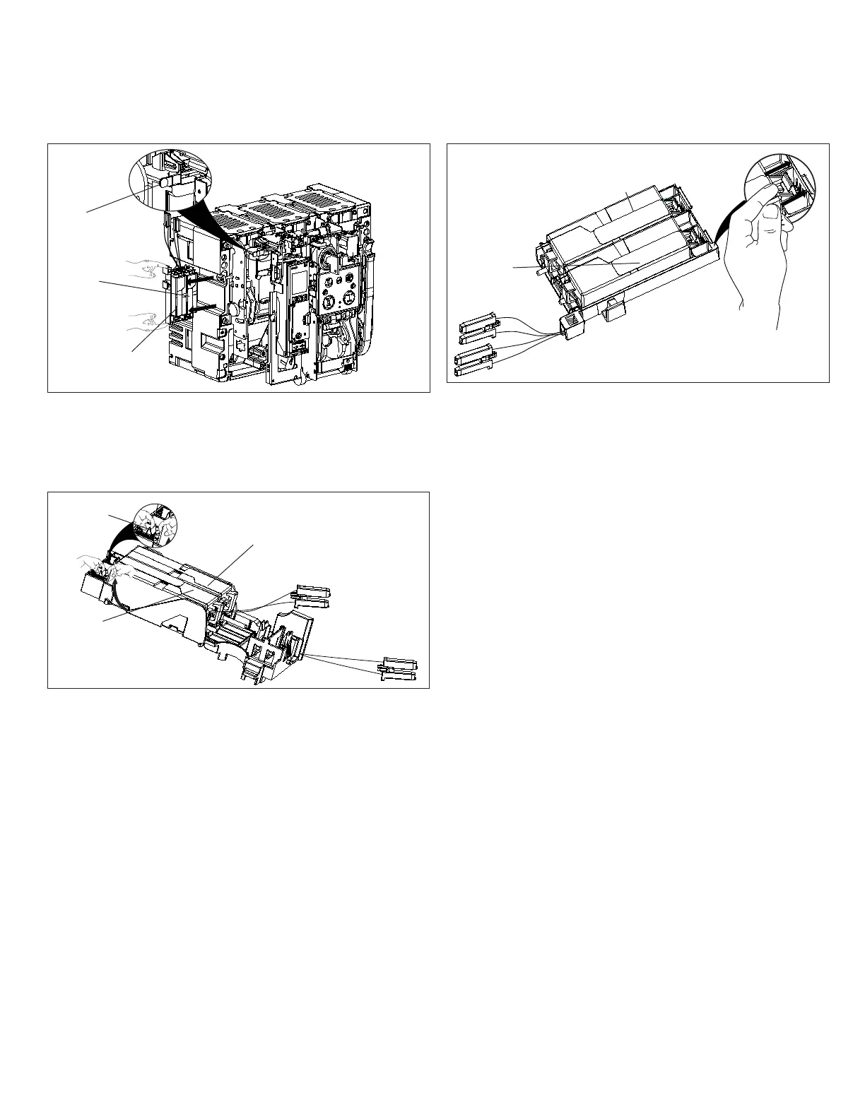
Figure 23. Step 4 (RF Frame Shown).
Step 5: Remove the UVR or ST by lifting it upward and out.
Step 6: Repeat Steps 4 and 5 if the other accessory is also to be
removed.
Step 7: If the tray will have a new ST and/or UVR installed, follow
steps 4 through 13 of Section 2. If not, just complete Steps 10
through 13 of Section 2.
ST
UVR
ST
ST
UVR
UVR
Thumb
Tab
Accessory Locking
Tab
 Loading...