COMMUNICATION
Eaton 9355 UPS (10/15 kVA) User's Guide S 164201594 Rev D www.eaton.com/powerquality
76
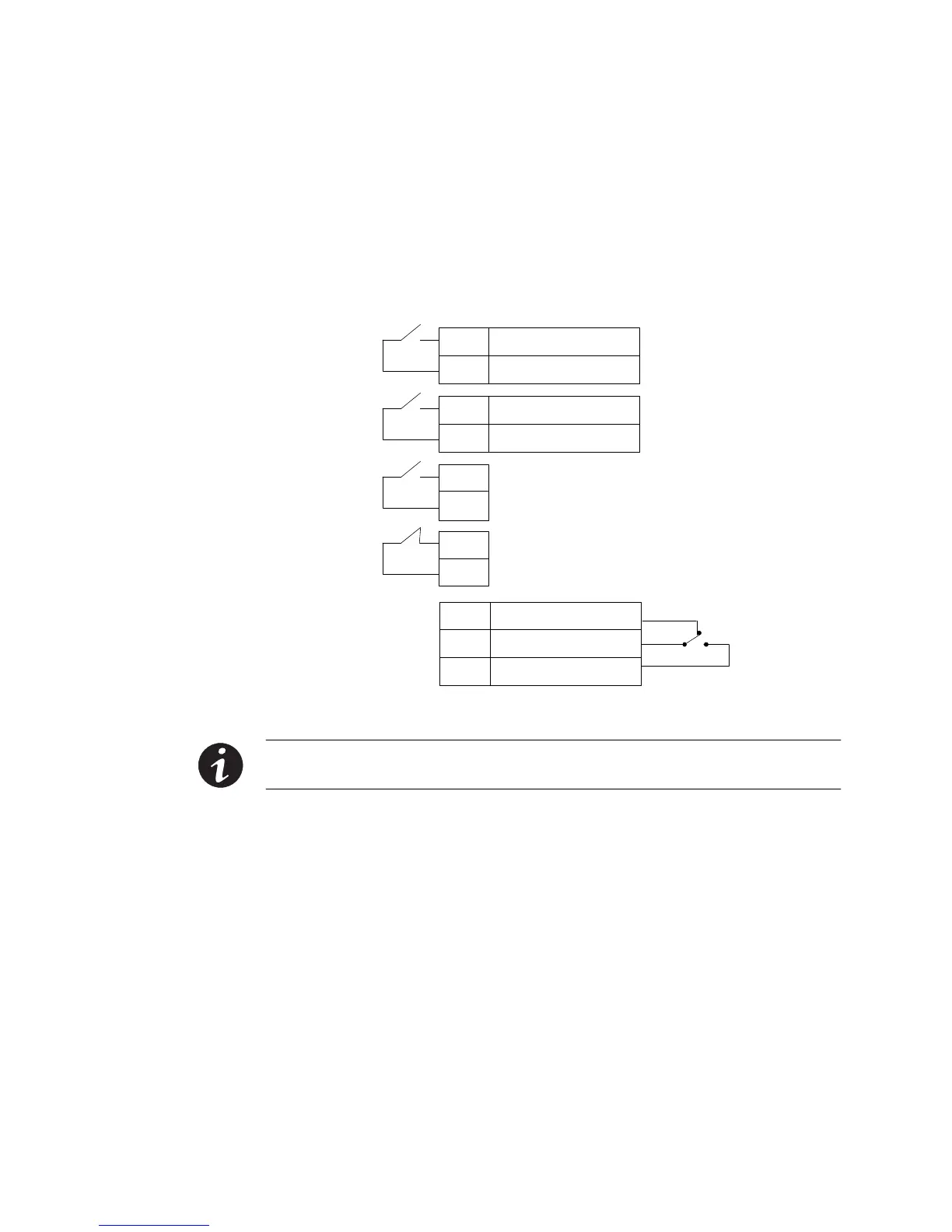
Control Terminals
The cables should be connected to the control terminals with a mating
connector. Input and output terminals have a functional isolation from
terminal to terminal. They are connected to the UPS chassis through
individual 1 MΩ resistors.
+ Polarity
– Polarity
2
1
+ Polarity
– Polarity
2
1
2
1
2
1
Signal Input 1 (programmable)
Signal Input 2 (programmable)
REPO Normally Open
REPO Normally Closed
Normally Open
Normally Closed
1
2
Common
3
Relay Output
UPS
Connectors
(see Figure 46 on
page 63)
Figure 57. External Control Terminal Connections
NOTE If using a semiconductor switch type, pay attention to the proper polarity. A relay or
other mechanical control is preferred.
 Loading...


