FIELD INSTALLED UPM INSTALLATION
EATON 9395 Field Installed UPM Mechanical Installation Manual S 164201717 Rev 3 www.eaton.com/powerquality
4−4
7. Locate the small flat bracket and screws from the hardware kit. Align the holes in
the small flat bracket over holes in the top of the FI−UPM and UPS cabinets.
Secure the bracket with the screws from the hardware kit.
8. Reinstall the FI−UPM front panel removed in Step 6, and secure with the retained
hardware.
9. If permanently mounting the system, proceed to Step 10; otherwise, continue to
Step 12.
10. Using the retained hardware, reinstall the left shipping bracket removed in
paragraph 4.2, Step 2 on page 4−1 to the left side of the FI−UPM cabinet with
the angle facing outward (see Figure 4-1 on page 4−2).
11. Secure the cabinet to the floor with customer−supplied hardware.
12. Proceed to paragraph 4.4.
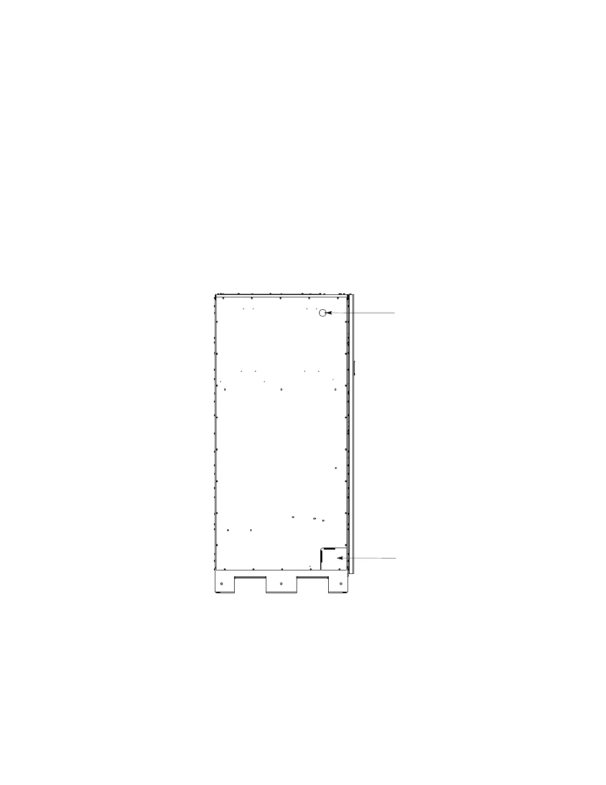
Wire Entry Plate Remove plate to
route wires between cabinets.
LEFT SIDE VIEW
UPS Front
Wire entry knockout. Remove knockout to
route wires between cabinets. (Install nylon
grommet after removal of knockout.)
Figure 4-3. UPS Cabinet Wire Entry Plate and Knockout Locations
 Loading...


