EasyManua.ls Logo

Ebyte E77-M22S Series User Manual

Ebyte E77-M22S Series
44 pages
To Next Page IconTo Next Page
To Previous Page IconTo Previous Page
Page #9 background image
Chengdu Ebyte Electronic Technology Co., Ltd. E77-xxxM22S User Manual
Copyright © 2012-2 024 , Chengdu Ebyte Electronic Technology Co., Ltd.
7
3 Mechanical Dimensions and Pin Definitions
3.1 Dimensional drawing
3.2 Pin definition
Pin
number
Pin name
Pin direction
Pin usage
1
PB3
input
Output
TX_LED, transmit data indication pin, output high level when
transmission is completed
2
PB4
input
Output
RX_LED, receive data indication pin, output high level after receiving
3
PB5
input
Output
LINK_LED, network access status indicator pin, outputs high level if
network access is successful
4
PB6
input
Output
USART1_TX (the built-in firmware is not used, reserved)
5
PB7
input
Output
USART1_RX (comes with firmware, not used, reserved)
6
PB8
input Output
Configurable general-purpose IO port (see STM32WLE5CCU6
manual for details)
7
PA0
input Output
Soft boot pin, pull it low continuously for 1s after power on to enter
Question and Answer IconNeed help?

Do you have a question about the Ebyte E77-M22S Series and is the answer not in the manual?

Ebyte E77-M22S Series Specifications

General IconGeneral
BrandEbyte
ModelE77-M22S Series
CategoryWireless modules
LanguageEnglish

Summary

Disclaimer and Copyright Notice

Product Overview

Introduction

Introduces the E77-400/900M22S LoRaWAN modules and their capabilities.

Features

Lists the key technical specifications and capabilities of the module.

Application scenarios

Details various use cases and applications for the module.

Specifications

RF parameters

Specifies radio frequency characteristics like frequency band, transmit power, and sensitivity.

Hardware parameters

Details hardware aspects like IC, Kernel, FLASH, RAM, and size.

Electrical parameters

Outlines electrical characteristics such as voltage, current, and operating temperature.

Parameter description

Explains the meaning and impact of various technical parameters.

Mechanical Dimensions and Pin Definitions

Dimensional drawing

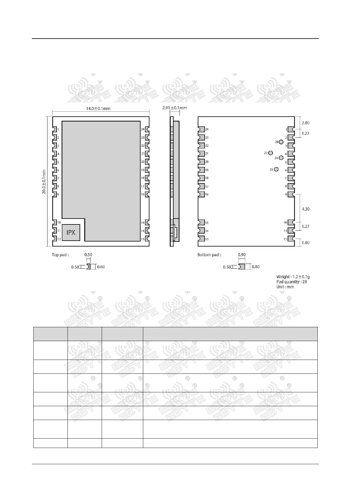
Provides visual representation of the module's physical dimensions.

Pin definition

Lists and describes each pin's function and direction.

Recommended connection diagram

Illustrates a typical circuit connection for the module.

Terms and Definitions

LoRa

Defines the LoRa technology and its characteristics.

LoRaWAN

Explains the LoRaWAN protocol and network structure.

ADR

Describes Adaptive Data Rate (ADR) in LoRaWAN for optimizing performance.

LoraWan application model diagram

Access Demonstration

AT Commands

Instruction format

Details the syntax and structure of AT commands.

AT command set

Lists all available AT commands and their general descriptions.

AT command description

Provides detailed explanations and examples for specific AT commands.

Secondary Development

Data Rates of Each Frequency Band

Maximum power of each frequency band

Maximum transmission load of each frequency band

Frequently Asked Questions

The communication distance is very close

Addresses issues related to short communication range and potential causes.

Modules are easily damaged

Provides precautions to prevent damage to the module.

Network access failed

Helps troubleshoot problems with network connectivity.

Important statement