14
Before you start
Before yo u start
Assembly
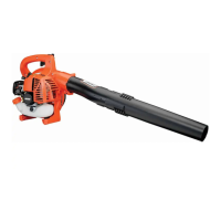
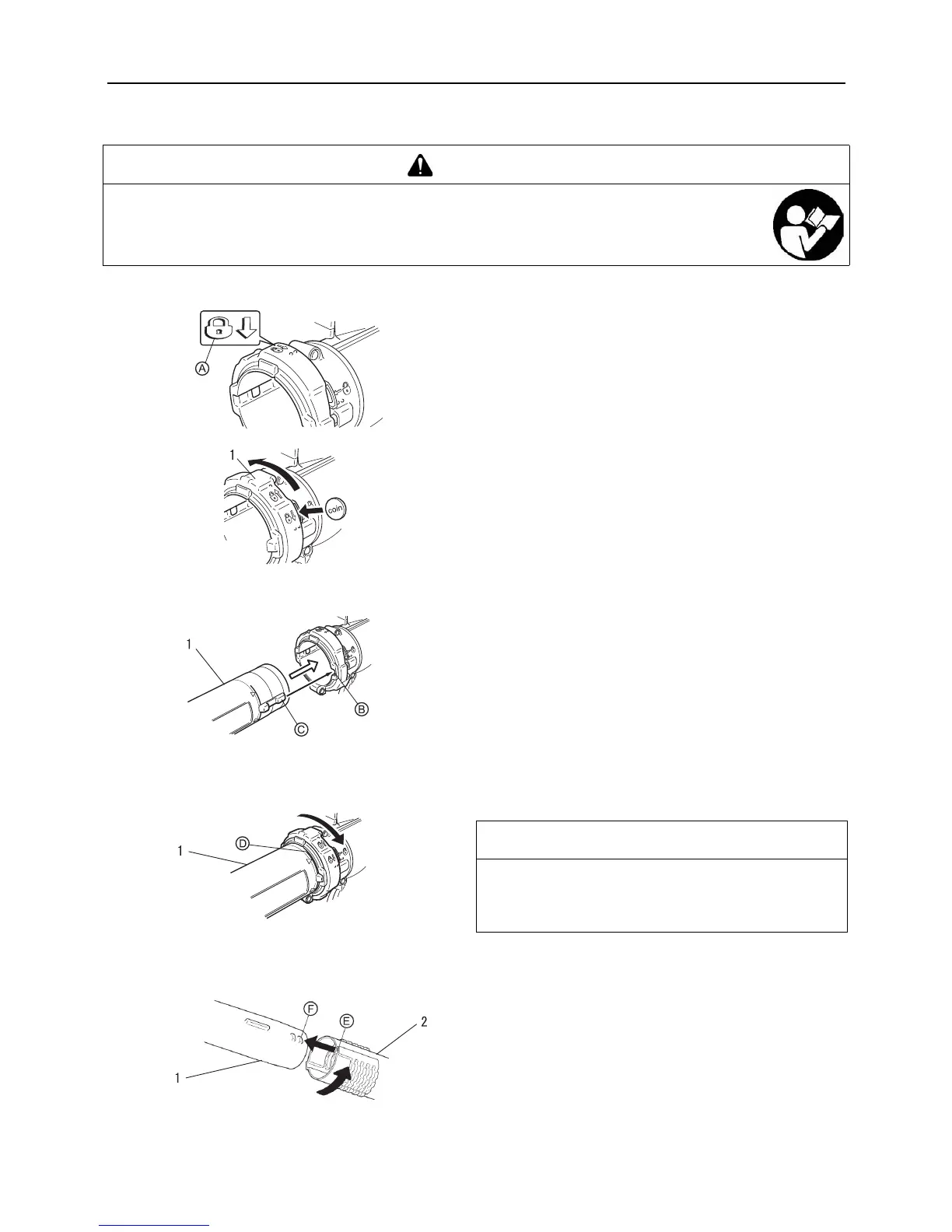
Install blower pipes
1. Stand unit upright on blower base.
2. Release locking ring with a coin or screwdriver, and rotate so
that lock symbol (A) is at top of ring.
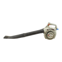
3. Align locking ribs (C) on the blower pipe(straight pipe) with
recesses (B) in locking ring, and slide the blower
pipe(straight pipe) into locking ring.
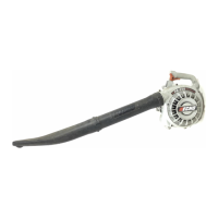
4. After inserting the blower pipe(straight pipe) into fan case so
that line (D) meets locking ring, rotate locking ring clockwise
1/8 turn to lock the blower pipe(straight pipe) in place.
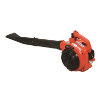
5. Align tabs (F) with grooves (E) and slide the blower pipe(fan
head nozzle) over the blower pipe(straight pipe) until there is
light resistance.
6. Assemble the blower pipe(fan head nozzle) onto the blower
pipe(straight pipe) until you feel light resistance. Do not
force connection. Hold the blower pipe(straight pipe), and
turn the blower pipe(fan head nozzle) clockwise, engaging
positive locking channels until connection is firm. Do not
force connection.
WARNING
Read the operator's manual carefully to ensure that you assemble the product correctly.
Never perform maintenance or assembly procedures with engine running.
Using a product that has been incorrectly assembled could lead to an accident or serious injury.
1. Locking ring
1. Blower pipe(straight
pipe)
1. Blower pipe(straight
pipe)
NOTE
Blower use will eventually loosen pipe connections. Exclusive
positive locking system allows pipes to be tightened. If loosen-
ing occurs, remove the blower pipe(fan head nozzle) and in-
stall according to instructions 5 & 6.
1. Blower pipe(straight
pipe)
2. Blower pipe(fan head
nozzle)
 Loading...