GRASS TRIMMER/BRUSH CUTTER
OPERATOR'S MANUAL
15
ASSEMBLY
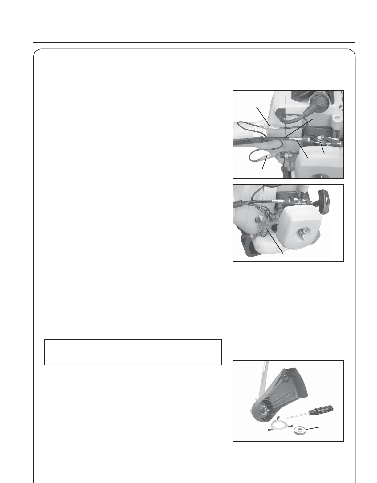
THROTTLE
LINKAGE AND IGNITION LEADS
(SRM-231U)
1. Connect ignition stop leads (A) and (B).
2. Place throttle linkage (C) through adjustment fixture (D) and install
wire end into large carburetor throttle swivel hole (E). Check throttle
for freedom of movement and that wide open throttle / low idle
extremes are adjusted properly. The throttle linkage must be
adjusted by moving the adjustment fixture (D). Consult with your
Echo Dealer for correct adjustment procedure.
3. Bundle and secure ignition leads against engine housing with clip
(F).
PLASTIC SHIELD INSTALLATION
(For Nylon Line Operation)
Tools Required: Screwdriver.
Parts Required: Plastic Shield, Shield Plate, three (3) 5mm x 15mm
screws.
NOTE
The plastic shield is for use with the Nylon Line Head only.
Install Metal Shield when using plastic or metal blades.
1A. (SRM-231) Remove vinyl protector from PTO shaft.
1B. (SRM-231U) Remove blade and metal shield , if installed.
2. Place plastic shield on bottom of bearing housing flange.
3. Place shield plate on plastic shield, align holes. Install three (3)
screws from bottom through plate and shield into gear case.
4. Install adapter plate (A) onto PTO shaft.
A
B
C
D
E
F
A
 Loading...