417101373_Ecodos-PCB.docx
Table of Contents
1 General 20
1.2 Extent of Warranty 20
1.3 Contact Address / Manufacturer 20
2 Safety 21
2.1 General safety information 21
2.2 Maintenance and repair work 21
2.3 Emphases 21
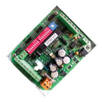
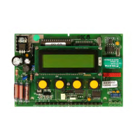
3 PCB Overview 22
3.1 Operation Mode 22
4 Functional description, operation and settings 23
4.1 Continuous mode 23
4.1.1 Settings 23
4.1.2 Enable Signals 23
4.2 Timed metering mode 23
4.2.1 Functional principal 23
4.2.2 Settings 24
4.2.3 Delay: (DIP switch “Delay | Mode |”) 24
4.2.4 Dosage time: (DIP switch “TIME/Titration”) 24
4.2.5 Enable signals 24
4.2.6 Fault indication 25
4.3 Conductivity mode 25
4.3.1 Controller function 25
4.3.2 Settings 26
4.3.3 Speed potentiometer for SOLID version (AC-output) 26
4.3.5 Titration: (DIP switch “TIME/Titration”) 27
4.3.6 Enable signals 27
4.3.7 Fault indication 28
4.4 Standby mode 28
4.5 Prime 28
4.6 Input signals 28
4.6.1 Low level mode / Capsule switch 28
4.6.2 Enable signal 28
5 Mounting and installation 29
5.1 Pre-installation requirements 29
5.2 Installation of conductivity sensor 29
5.3 Electrical connection 29
5.4 Wiring diagram 30
5.5 Possible input modules (connection at IN1) 31
6 Maintenance and repair instructions 32
6.1 Replacement of PCB 32
6.2 Replacement of buzzer 32
7 Trouble shooting 33
8 Spare parts list 34
9 Technical data 35
 Loading...