en
5
PRODUCT IDENTIFICATION
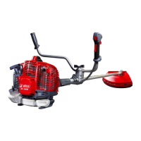
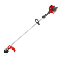
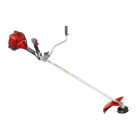
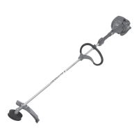
MAIN COMPONENTS (Fig.1)
1÷3 - Tools supplied
4 - Harness
5 - Bevel gear
6 - Curved guard
7 - Nylon line head
8 - Fuel tank cap
9 - Purge Bulb
10 - Carburettor adjustment screws
11 - Mu er guard
12 - Spark plug
13 - Air lter
14 - Starter Handle
15 - Choke Lever
16 - Throttle trigger lockout
17 - STOP button
18 - Throttle lever
19 - Harness attachment
20 - Handle
21 - Shaft arm
22 - Button half-throttle
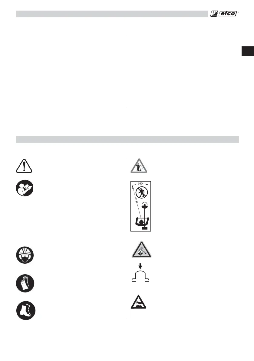
SAFETY
- This symbol indicates Warning,
and Caution.
- Your manual contains special
messages to bring attention
to potential safety concerns,
machine damage as well as
helpful operating and servicing
information. PLEASE READ
ALL THE INFORMATION
CAREFULLY TO AVOID INJURY
AND MACHINE DAMAGE.
- Wear eye, hearing and head
protection when operating this
equipment.
- Wear non-slip, heavy-duty
protective gloves when handling
the brush cutter and blades.
- Wear safety strong shoes or
boots having skid-proof sole and
anti-piercing insert.
- Be aware that objects can be
thrown.
- Keep bystanders away 50 ft (15
m).
- Warning! Kickback it’s danger.
- Purge bulb.
- WARNING – The surface can be
hot.
Understanding Safety Symbols
 Loading...