Operation
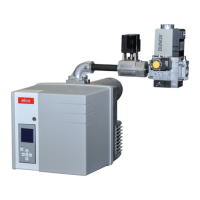
MB-ZRDLE gas train
MBZRDLE... B01S.. (dual-stage)
Compact unit consisting of:
filter, adjustable pressure switch, non-
adjustable rapid opening and closing
safety valve, adjustable pressure
regulator, main valve (first and second
stage) with adjustable throughput and
hydraulic brake, plus rapid closing.
Default setting:
- Flow rate 1
st
stage and 2
nd
stage, set
to maximum.
- Ignition flow rate and pressure
regulator set to minimum.
Technical data
Input pressure 360 mbar max.
Ambient temperature -15 to +70 C°
Voltage 230 V/ 50 Hz
Absorbed output 60 VA
Protection level IP 54
Gas connection 3/4" Rp or 1" 1/4 Rp
Assembly position:
- Vertical with coil facing upwards
- Horizontal with coil hidden
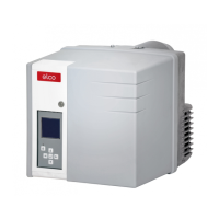
Pressure regulator setting
The adjusting screw has a path of 60
turns for adjusting the output pressure.
Three turns clockwise or anticlockwise
increases or reduces pressure by
1 mbar respectively.
At commissioning:
• Turn the screw at least 10 turns
clockwise (+)
• Then fine tune the adjustment (more or
less pressure)
• Checking the gas pressure on the
pressure tap 119pBr.
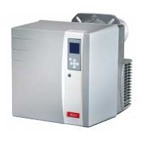
Setting the ignition throughput
• Unscrew plastic cap B.
• Turn it over and use it as a tool for
turning the adjusting screw (three
turns to adjust from minimum to
maximum throughput)
• Reduce the ignition throughput by
turning the screw clockwise, reduce it
by turning it anti-clockwise.
Adjusting the nominal flow rate
• Unscrew the locking screw (the sealed
screw must not, however, be
unscrewed)
Setting the gas throughput for
the 2
nd
stage
• Reduce nominal gas throughput by
turning adjusting knob C, anti-
clockwise (located on the upper
section of the solenoid coil). Turning
clockwise increases throughput.
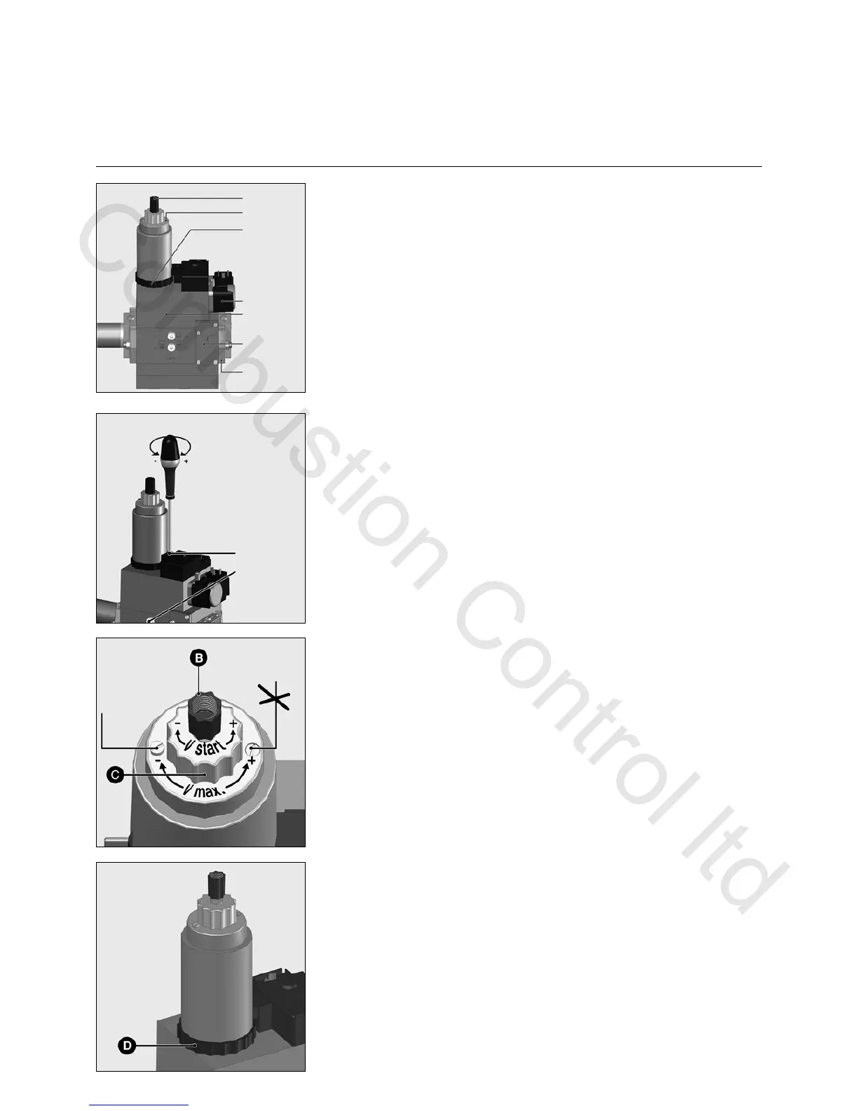
Setting the gas throughput for
the 1
st
stage
By hand (not tool).
• Reduce gas throughput by turning ring
D clockwise (located on the lower
section of the solenoid coil). Turn anti-
clockwise to increase gas throughput.
 Loading...