02/2011 - Art. Nr. 4200 1027 9501B14
Commissioning
Adjustment data
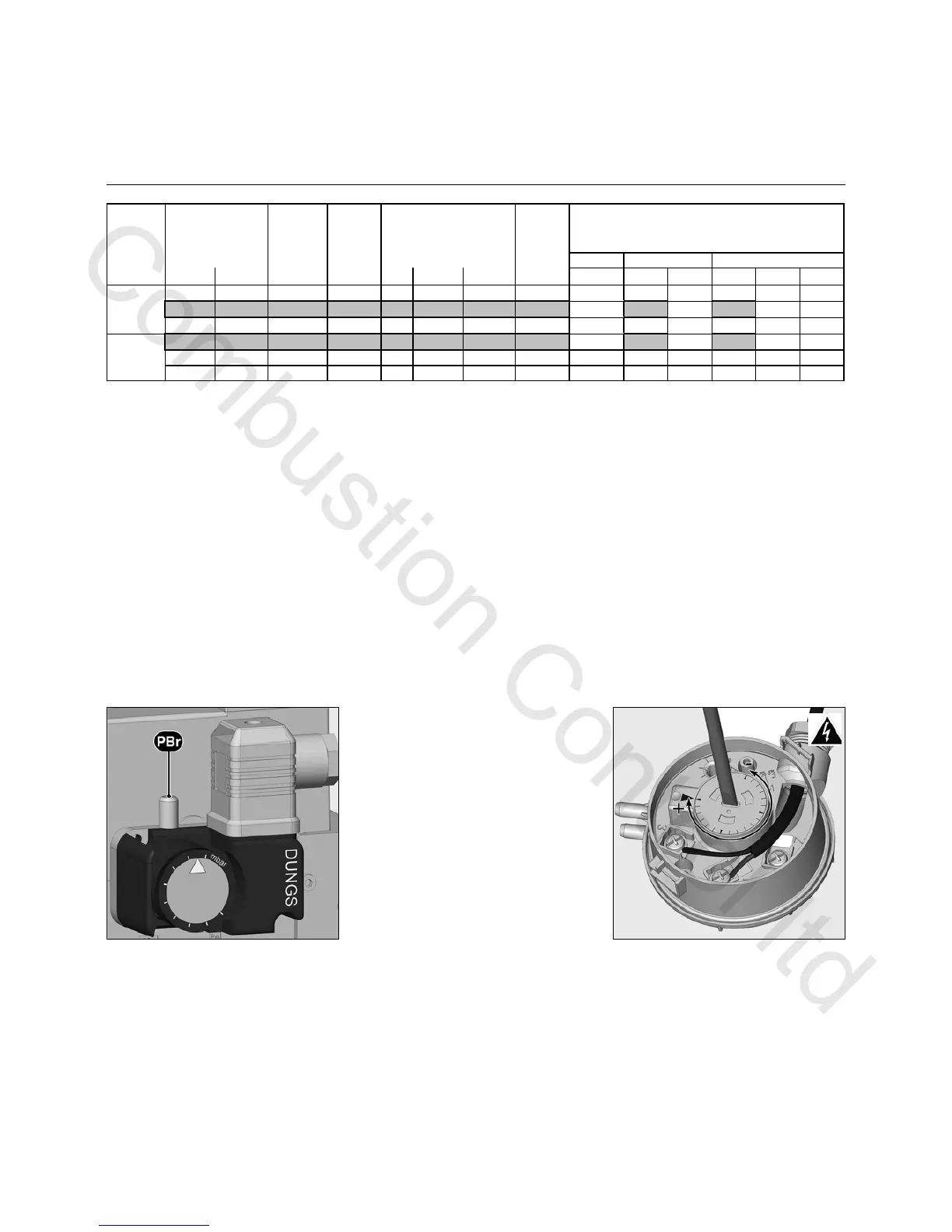
Setting the gas pressure switch
• Remove the transparent cover.
• Provisionally set to 15mbar.
Setting the air pressure switch
• Remove the transparent cover.
• Provisionally set to 1 mbar.
15 - 1,3 / 5,3 1,6 / 6,3 2 / 6,3 2,3 / 7,7 1,3 / 4,8
140 220 40 2,5 15 15 38 20 - 2,8 / 7 3,3 / 8,1 4,7 / 8 4,8 / 10 2,7 / 6,3
190 250 40 2,7
35 - 4,7 / 8,5 6 / 9,8 6,2 / 9 8,3 / 12,3 4,6 / 7,5
125 230 40 2,5 8 8 33 15 2,2 / 7,7 2,5 / 7 2,8 / 8,3 3 / 8,3 3,8 / 10,5 2,3 / 6,2
180 270 40 3 22 22 48 30 4,4 / 10,7 4 / 9,6 5 / 11,3 5,5 / 11,7 7,1 / 14,7 3,7 / 8,5
240 310 40 3,3 38 38 75 45 8,1 / 13 7,3 / 11,4 8,7 / 13,5 9,8 / 14,4 12,4 / 18 7,1 / 10,5
VG3.290 D
VG3.360 D
2
d
stage
val ve
opening MB-...412 MB-...407
Burner power
Dime n si o n
Y
(mm)
Furnace
pressure
pF
(mbar)
Gas valve setting
Gas head pressure pBr (mbar)
1. stage / 2. stage
Air flap setting
The adjustment values above are guide
values and facilitate commissioning.
The factory settings are in bold set
against a grey background The final
settings are essential in ensuring that
the burner functions as well as possible
 Loading...