108
Epsilon Eb and EN Drives Reference Manual
The default encoder output scaling is set to output the actual motor encoder resolutions. The
standard MG and NT motors have 2048 lines per revolution. With PowerTools this resolution
is adjustable in one line per revolution increments up to the density of the encoder in the
motor.
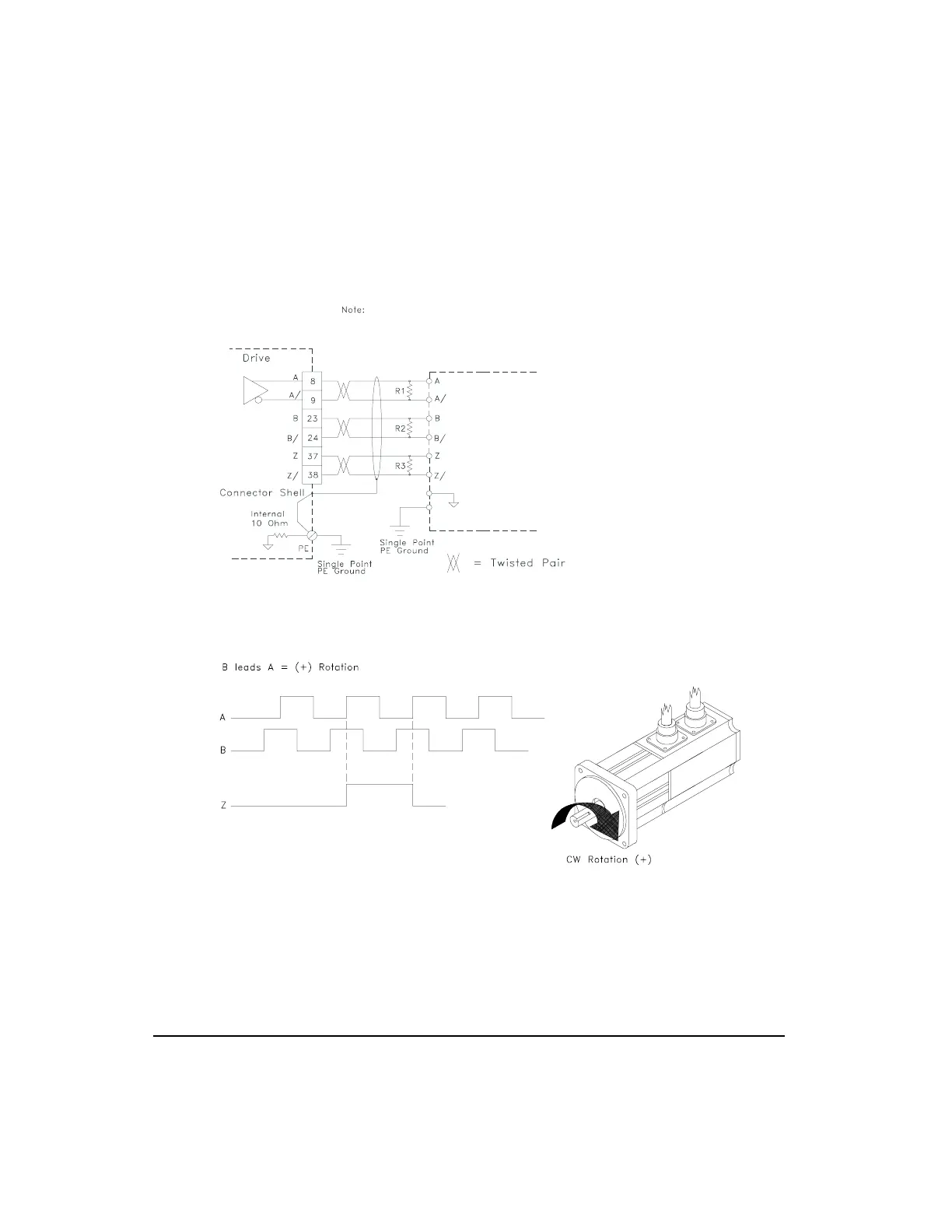
Figure 80: Command Connector Encoder Output Wiring
Figure 81: Direction Convention Diagram
If the external controller does not have an internal terminating resistor
R1, R2 and R3 must be mounted within 6 inches of the external controller. A
120 ohm resistor is recommended for high frequency encoders (over 250 kHz)
or cables longer than 25 feet. If encoder signals are multi-dropped, termination
resistors are required only at the last drop point. Do not terminate at more than
one point.
External
Controller
Encoder
Input
Artisan Technology Group - Quality Instrumentation ... Guaranteed | (888) 88-SOURCE | www.artisantg.com
 Loading...