AGL_HP_VS_YHV_RG_RT_EN_Rev00 17
In order to ensure positive compressor protection, discharge gas temperature protection is required
for any application with Copeland compressors.
The maximum discharge gas temperature is 135 °C for all YHV*RG and YHV*RT models.
Discharge gas temperature protection is the "fall-back" for failure of the system control. It is essential
that proper control of both the evaporating and condensing pressures and the superheat is
maintained and has the ability to cope with all likely conditions and high loads. Reliance on protectors
will cause inadequate system performance and short cycling.
NOTE: The maximum discharge gas temperatures indicated in this chapter are valid for safe
operation within the approved application envelope. The discharge temperature protection
has the function of a compressor protection device; it is not designed to control the operating
envelope. For compressor envelope and superheat control, a dedicated control device must
be used.
3.7.1 Excessive discharge gas temperatures
A few of the possible consequences of excessive discharge gas temperatures are listed below:
Since the oil circulates in the system with the ref rigerant, it is subjected to high discharge gas
temperatures. If the discharge gas temperature becomes too high, the so-called "cooking" effect
will occur (heating of oil under exclusion of air). Carbon deposits can form at points of high
temperature, for example on the valves, oil channels, oil filters, etc. The oil lubricity will be reduced
and a progressive wear process will occur which will prematurely damage the compressor.
The stability of the ref rigerant can also be affected, particularly if traces of contaminant are
present.
The problems described above f requently occur simultaneously, particularly since the chemical
reaction speed approximately doubles with every 10 °C temperature rise. This directly leads to
chemical reactions of the oil with the refrigerant and the compounds extracted from sealants and
insulation material. As a consequence, contaminants of various types, among them acids, will form
inside the system.
3.7.2 Discharge line temperature sensor
Variable-speed compressors need an external Discharge Line Temperature (DLT) sensor. The
correct reading of the sensor is fundamental for discharge line temperature control. The sensor must
ensure good accuracy and acceptable dynamic behaviour.
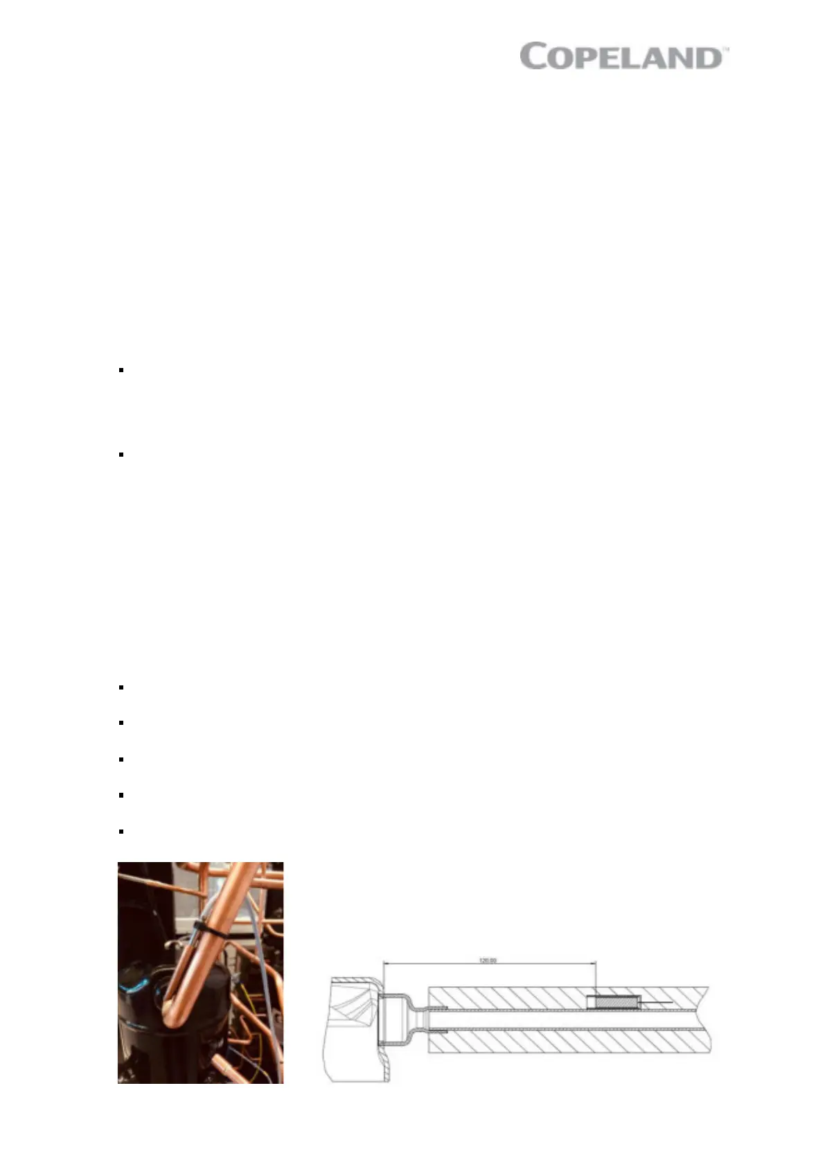
Please follow the recommendations below for sensor assembly:
The DLT sensor must be attached to the compressor discharge line at a distance of 120 mm from
the compressor discharge fitting.
The sensor must be installed in a copper sleeve, to improve response time and to reduce setoff.
The copper sleeve must be brazed on the surface of the pipe.
Use thermal compound to improve heat transfer from sleeve to sensor. The thermal compound
must be approved for the applied temperature ranges.
For best response and to reduce the impact of ambient temperature the pipe including the sensor
must be insulated.
Protect the sensor f rom being moved or removed from its position by transport, vibration or any
other incident.
Figure 16: Discharge temperature sensor mounting
 Loading...