22 AGL_HP_VS_YHV_RG_RT_EN_Rev00
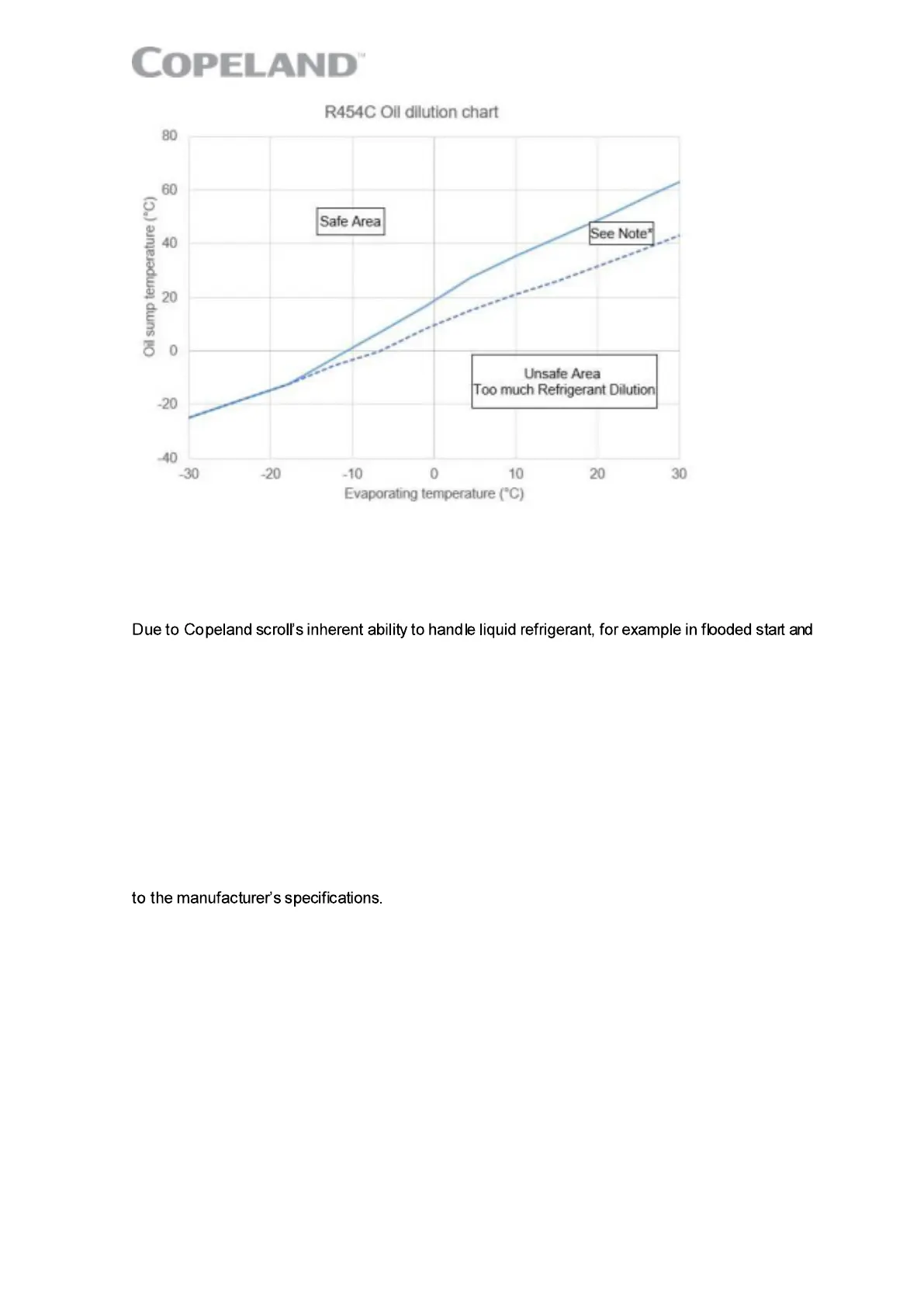
Figure 19: Oil dilution chart for R454C and POE 4MA (tb = bottom shell temperature; te = evaporating temperature)
NOTE: Low-load operation may be acceptable between the continuous and dashed lines.
Please contact the Application Engineering department at Emerson for more information.
3.16 Suction line accumulator
defrost cycle operation, an accumulator is not required in most systems.
To determine if a suction line accumulator is required, the system designer must check this with an
appropriate test scenario. See section 3.15 "Compressor oil return, oil balancing, floodback and
oil dilution tests".
If an accumulator is used, the oil-return orifice should be from 1 to 1.4 mm in diameter for all
YHV*RG/RT models depending on compressor size and compressor f loodback results. To protect
this small orifice from plugging with system debris a large-area protective screen no finer than 30 x
30 mesh (0.6 mm openings) is required. Tests have shown that a small screen with a fine mesh can
easily become plugged causing oil starvation to the compressor bearings. The size of the
accumulator depends upon the operating range of the system and the amount of sub-cooling and
subsequent head pressure allowed by the refrigerant control. System modelling indicates that heat
pumps operating down to and below -18 °C will require an accumulator that can hold around 70 to
75 % of the system charge. For the correct selection and size of the suction line accumulator, refer
The behaviour of the accumulator and its ability to prevent liquid slugging and subsequent oil pump-
out at the beginning and end of the defrost cycle should be assessed during system development.
This will require special accumulators and compressors with sight tubes f or monitoring refrigerant
and oil levels.
Check with the suppliers whether an extra charge of oil for the suction accumulator is required. If
necessary, pre-charge additional oil to the system accordingly.
 Loading...