Instruction Manual
D104161X012
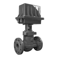
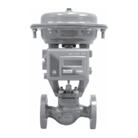
D3 Valve with Gen 2 easy-Drive Actuator
February 2021
10
Default Input Signals
The D3 with easyDrive comes from the factory calibrated and ready for use with the following default input signals
shown in table 2.
Table 2. D3 easy-Drive Default Input Signals
CONFIGURATION ON/OFF POSITIONING
Input Signal L2e (dual dry contact) 4-20 mA
If the input signal of the application matches table 2, proceed to the Wiring Instructions section. If the input signal of
the application does not match table 2, proceed to the Configuration section.
Configuration
Input Configuration
There are 2 functional configurations available for the easyDrive electric actuator: On/Off and Positioning. It is
possible to change an actuator from On/Off to Positioning after it has been delivered from the factory using a
positioning license key. See licensing section.
All available input signals are shown in table 3.
Table 3. All Available Input Signals
CONFIGURATION ON/OFF POSITIONING
Control Source Modbus Local Modbus Local
Input Signal Modbus
L2e Dual Dry Contact
(default)
Single Dry Contact Modbus 4-20 mA (default)
If you are using the default inputs signals, and the valve has not been disassembled or adjusted in any way, there is no
need to recalibrate the assembly. You can proceed directly to Startup (page 17).
Changing the Inputs from Default Settings
All configuration within the valve is done by setting values in Modbus registers. This can be done using any Modbus
master (flow computer, PLC, PC). Configuration software, providing a visual interface to the registers, is available
through your Emerson sales office
.
Modbus setup
Use of a serial or USB to RS-485 device is required to connect to the actuator. Refer to manufacturer's requirements for
installation. The D3 with easyDrive electric actuator Modbus factory defaults are Address 1, 9600 baud, even parity, 1
stop bit, MSB.
When a connection has been achieved, the actuator may be configured to accept the input signal over the Modbus
link (ignoring the physical inputs) and the Modbus settings may be changed to accommodate the network to which it
is attached. Other changes to functionality are possible, such as:
D Low level cutoff: 40054 (default is 5%)
D Position upon loss of signal: 40053 (default is 0%)
See Appendix A for a full map of Modbus registers and their functions.

 Loading...