EDR and ETR Valves
Instruction Manual
Form 5050
August 2006
3
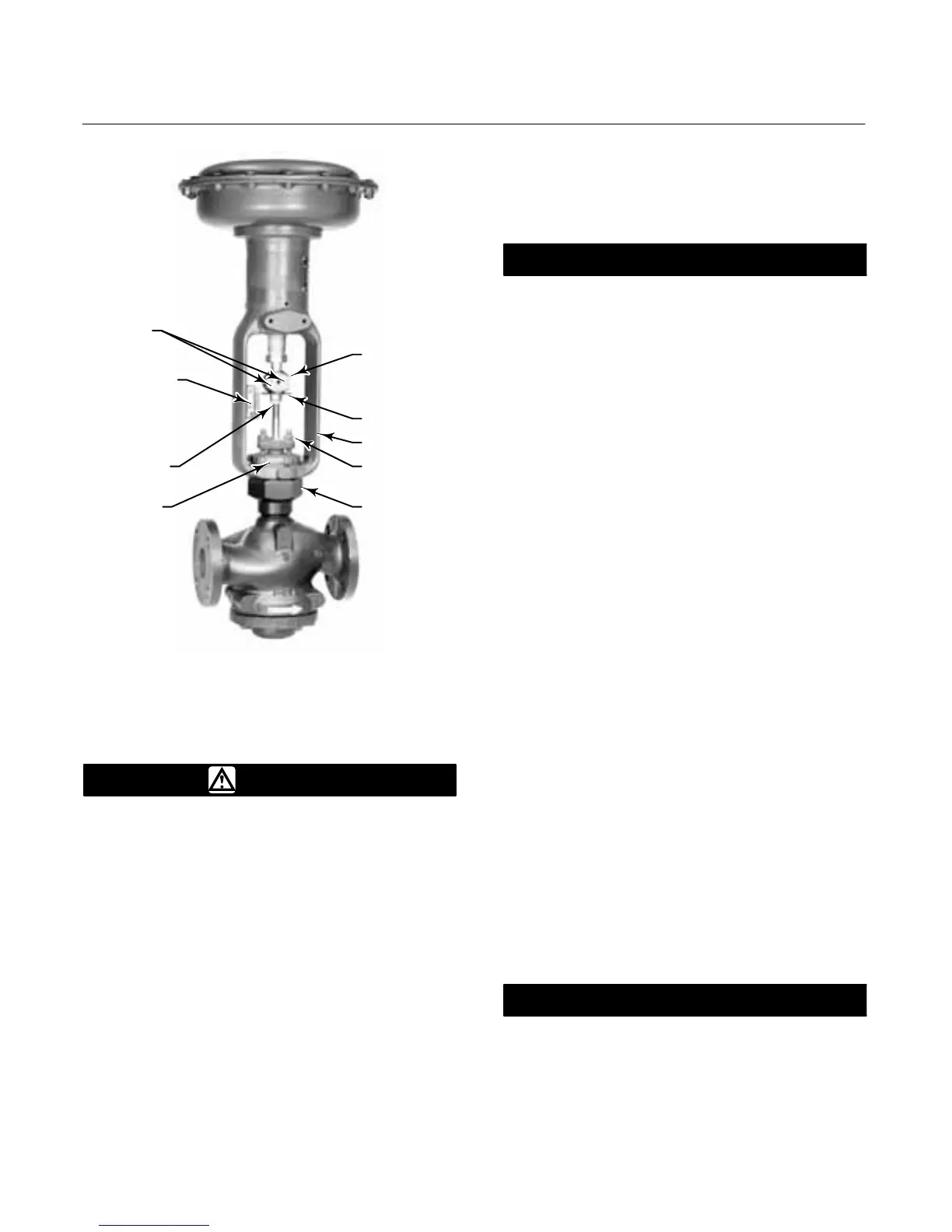
CAP SCREWS
INDICATOR SCALE
STEM LOCKNUTS
YOKE LOCKNUT
STEM
CONNECTOR
INDICATOR DISK
ACTUATOR
YOKE
PACKING
FLANGE
NUTS
BONNET
W2080-1 / IL
Figure 2. Actuator Mounting
Installation
WARNING
Always wear protective gloves,
clothing, and eyewear when
performing any installation operations.
To avoid personal injury or property
damage resulting from the sudden
release of pressure, do not install the
valve assembly where service
conditions could exceed the limits
given on the valve and actuator
nameplates. Use pressure-relieving
devices as required by accepted
industry, local, state, or Federal codes,
and good engineering practices.
Check with your process or safety
engineer for any other hazards that
may be present from exposure to
process media.
If installing into an existing
application, also refer to the WARNING
at the beginning of the Maintenance
section in this instruction manual.
CAUTION
The valve configuration and
construction materials were selected
to meet particular pressure,
temperature, pressure drop, and
controlled fluid conditions. Because
some body/trim material combinations
are limited in their pressure drop and
temperature range capabilities, do not
exceed these conditions without first
contacting your Emerson Process
Management sales office.
Inspect the valve and pipelines to
ensure they are not damaged, are
clean, and free of foreign material.
1. Before installing the valve, inspect the valve and
associated equipment for any damage and any
foreign material.
2. Make certain the valve body interior is clean, that
pipelines are free of foreign material, and that the
valve is oriented so that pipeline flow is in the same
direction as the arrow (see figure 2) on the side of
the valve.
3. The control valve assembly can be installed in
any orientation unless limited by seismic criteria.
However, the normal method is with the actuator
vertical above the valve body (see figure 2). Other
positions may result in uneven valve plug and cage
wear, and improper operation. With some valves, the
actuator may also need to be supported when it is
not vertical. For more information, consult your
Emerson Process Management sales office.
4. Use accepted piping and welding practices when
installing the valve in the line. If a post-weld heat
treatment process is to be applied to the valve end
connections, and the valve has composition or
elastomer trim parts, remove the trim to avoid
damage to the soft parts.
CAUTION
Depending on valve body materials
used, post weld heat treating may be
required. If so, damage to internal
elastomeric and plastic parts, as well
as internal metal parts is possible.

 Loading...


