*Recommended spare
19. Available in Feedback Unit Kit
21. Available in Feedback Unit Termination Strip Kit
DVC6000 Digital Valve Controllers
September 2013
8-6
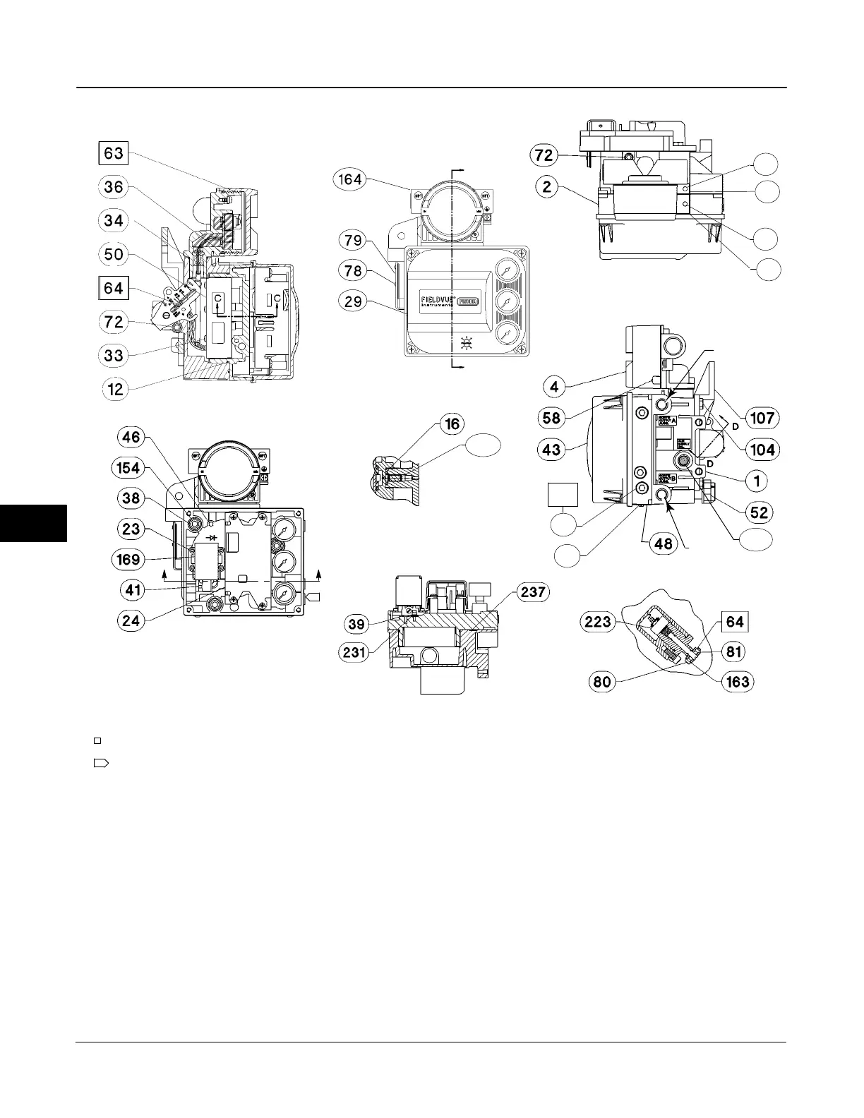
Figure 8-2. FIELDVUE DVC6010 Digital Valve Controller Assembly
APPLY LUB, SEALANT
SECTION A-A
SECTION E-E
E
E
SECTION D-D
1
1
NOTES:
SEE FIGURE 8-6 FOR GAUGE CONFIGURATIONS
2. APPLY LUBRICANT KEY 65 TO ALL O−RINGS UNLESS OTHERWISE
SPECIFIED
OUTPUT A
OUTPUT B
SUPPLY
SECTION C-C
A
A
48B7710−K SHT 1 & 2 / DOC
11
11
19
20
271
61
49
64
243
Key Description Part Number
131 Retainer Wire
251 Feedback housing
(19)
252 Assembly Plate Shield
(19)
(DVC6015 only)
253 Terminal bracket
(19,21)
254 Terminal Strip
(19,21)
255 Terminal Cap
(19)
256 O−ring, fluorosilicone
(19)
257 Machine Screw, pan head
(19)
(2 req’d) (DVC6015 only)
258 Label, cover
(19)
260 Hex Nut, SST (2 req’d)
Key Description Part Number
261 Nameplate
265 Plug
(19)
(DVC6015 and DVC6035 only)
HART Filters
HF340, DIN rail mount 39B5411X022
HF341, DIN rail Mount, pass through (no filter) 39B5412X012
8

 Loading...


