DVC6000 Digital Valve Controllers
September 2013
2-24
WARNING
To avoid personal injury or property
damage caused by fire or explosion,
remove power to the instrument
before removing the terminal box
cover in an area which contains a
potentially explosive atmosphere or
has been classified as hazardous.
4-20 mA Loop Connections
The digital valve controller is normally powered by a
control system output card. The use of shielded cable
will ensure proper operation in electrically noisy
environments.
WARNING
To avoid personal injury or property
damage from the sudden release of
process pressure, be sure the valve is
not controlling the process. The valve
may move when the source is applied.
Wire the digital valve controller as follows: (unless
indicated otherwise, refer to figures 8-2 through 8-4 for
identification of parts).
1. Remove the terminal box cap (key 4) from the
terminal box (key 3).
2. Bring the field wiring into the terminal box. When
applicable, install conduit using local and national
electrical codes which apply to the application.
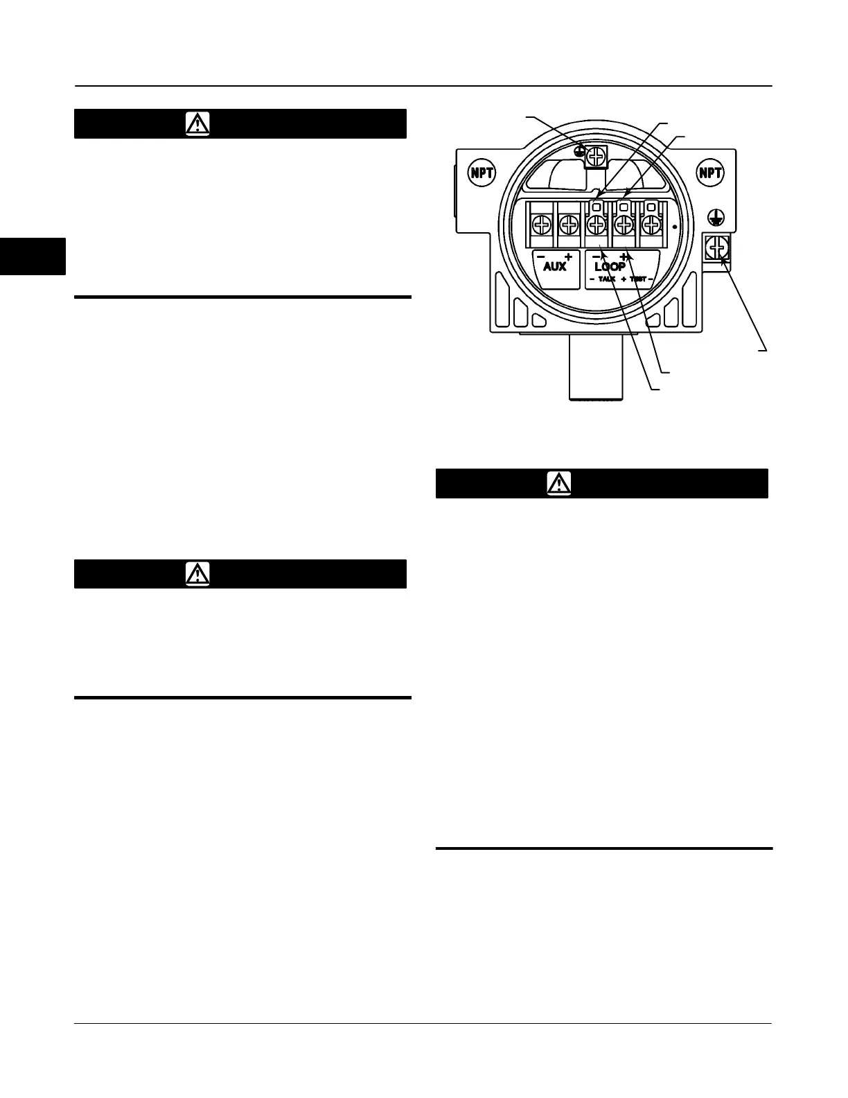
3. Refer to figure 2-20. Connect the control system
output card positive wire ‘‘current output’’ to the LOOP
+ screw terminal in the terminal box. Connect the
control system output card negative (or return) wire to
the LOOP − screw terminal.
SAFETY GROUND
LOOP−
LOOP+
EARTH GROUND
TALK+
TALK−
39B3399-B Sheet 2
Figure 2-20. FIELDVUE DVC6000 Digital Valve Controller
Terminal Box
WARNING
Personal injury or property damage,
caused by fire or explosion, can
result from the discharge of static
electricity. Connect a 14 AWG (2.08
mm
2
) ground strap between the
digital valve controller and earth
ground when flammable or
hazardous gases are present. Refer
to national and local codes and
standards for grounding
requirements.
To avoid static discharge from the
plastic cover when flammable gases
or dust are present, do not rub or
clean the cover with solvents. To do
so could result in a spark that may
cause the flammable gases or dust
to explode, resulting in personal
injury or property damage. Clean
with a mild detergent and water
only.
4. As shown in figure 2-20, two ground terminals are
available for connecting a safety ground, earth ground,
or drain wire. These ground terminals are electrically
identical. Make connections to these terminals
following national and local codes and plant standards.
5. Replace and hand tighten the terminal box cap.
When the loop is ready for startup, apply power to the
control system output card.
2

 Loading...


