Quick Start Guide
D103556X012
DVC6200 Digital Valve Controllers
July 2017
11
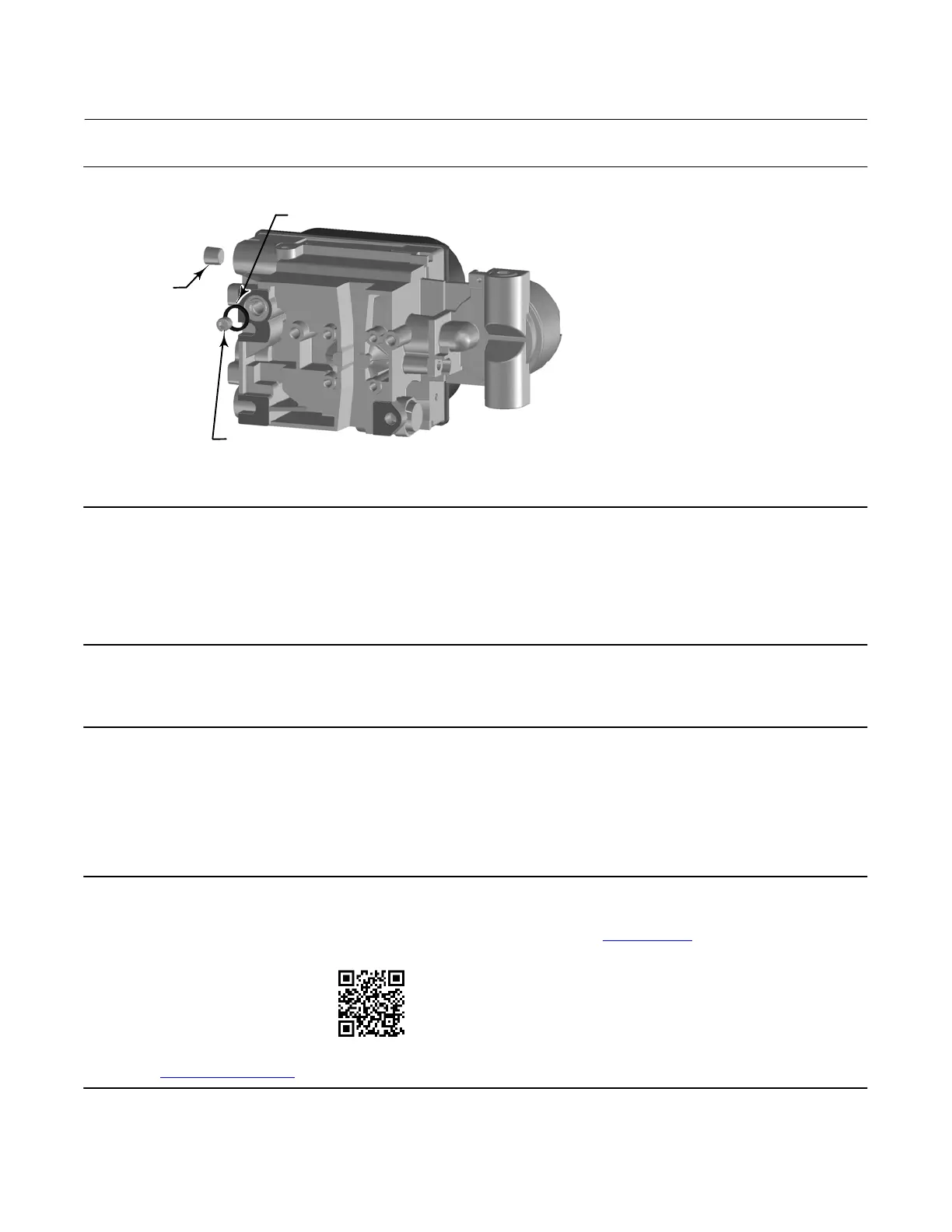
Figure 8. Modifications for Integral Mounted Actuator; Air‐to‐Open Construction Only
INSTALL O‐RING
INSTALL
1/4 NPT PLUG
REMOVE R1/8 PLUG
W9707
NOTE:
REAR HOUSING VIEW FOR GX ACTUATOR ILLUSTRATED
3. Install the plug (1/4 NPT, included in the mounting kit) to the external output pneumatic port A.
4. Attach the digital valve controller to the actuator mounting pad on the side that has the open pneumatic port. Be
sure to place the O‐ring between the digital valve controller's pneumatic output and the actuator mounting pad.
Pneumatic tubing is not required because the air passages are internal to the actuator.
Note
Use a 5 mm hex key to attach the digital valve controller the GX actuator mounting pad.
Use a 13 mm socket or box end wrench to attach the digital valve controller to the 667 size 30i -76i actuator mounting pad.
5. Check for clearance between the magnet assembly and the DVC6200 feedback slot.
6. If not already installed, install a vent in the port on the upper diaphragm casing.
7. For remote mount applications, proceed to page 17 for DVC6205 base unit mounting. Otherwise, proceed to
Step 2—Connect the Pneumatic Tubing on page 19.
Note
Refer to the 667 Diaphragm Actuator Sizes 30/30i - 76/76i and 87 instruction manual (D100310X012
) for 667 product
information.
Scan or click the code to see
how to mount a DVC6200 digital
valve controller to a 667 actuator
with integrated mounting pad
Refer to the GX instruction manual
for GX product information.

 Loading...


