Quick Start Guide
D103556X012
DVC6200 Digital Valve Controllers
July 2017
8
Actuators over 210 mm (8.25 inches) Travel
1. Isolate the control valve from the process line pressure and release pressure from both sides of the valve body. Shut
off all pressure lines to the pneumatic actuator, releasing all pressure from the actuator. Use lock‐out procedures to
be sure that the above measures stay in effect while working on the equipment.
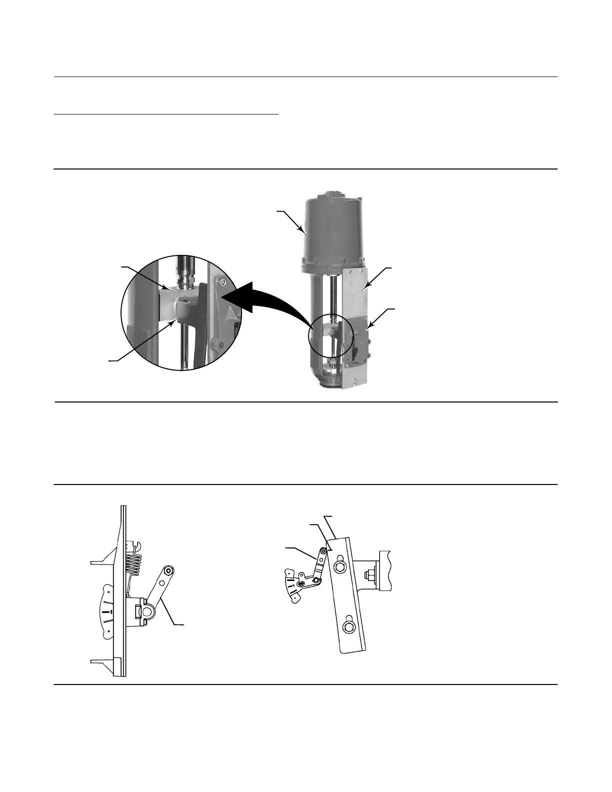
Figure 5. Mounting on Sliding‐Stem (Linear) Actuators over 210 mm (8.25 Inches) Travel
LONG STROKE MOUNTING KIT
(DVC6200 NOT SHOWN)
MOUNTING ADAPTOR
W9709
ACTUATOR
VALVE STEM
CONNECTOR
CAM
2. Install the cam to the valve stem connector as described in the instructions included with the mounting kit.
3. Install the mounting adaptor to the actuator.
4. Attach the digital valve controller and mounting kit assembly to the mounting adaptor. The roller on the digital
valve controller feedback arm will contact the actuator cam as it is being attached.
Figure 6. Roller Arm Variation used for Sliding‐Stem (Linear) Actuators over 210 mm (8.25 Inches) Travel
ROLLER
ARM
E1229
CAM
CAM/ROLLER
POSITION MARK
ACTUATOR IS FULLY EXTENDED
ROLLER ARM
E1543
5. For remote mount applications, proceed to page 17 for DVC6205 base unit mounting. Otherwise, proceed to
Step 2—Connect the Pneumatic Tubing on page 19.

 Loading...


