Quick Start Guide
D103556X012
DVC6200 Digital Valve Controllers
July 2017
7
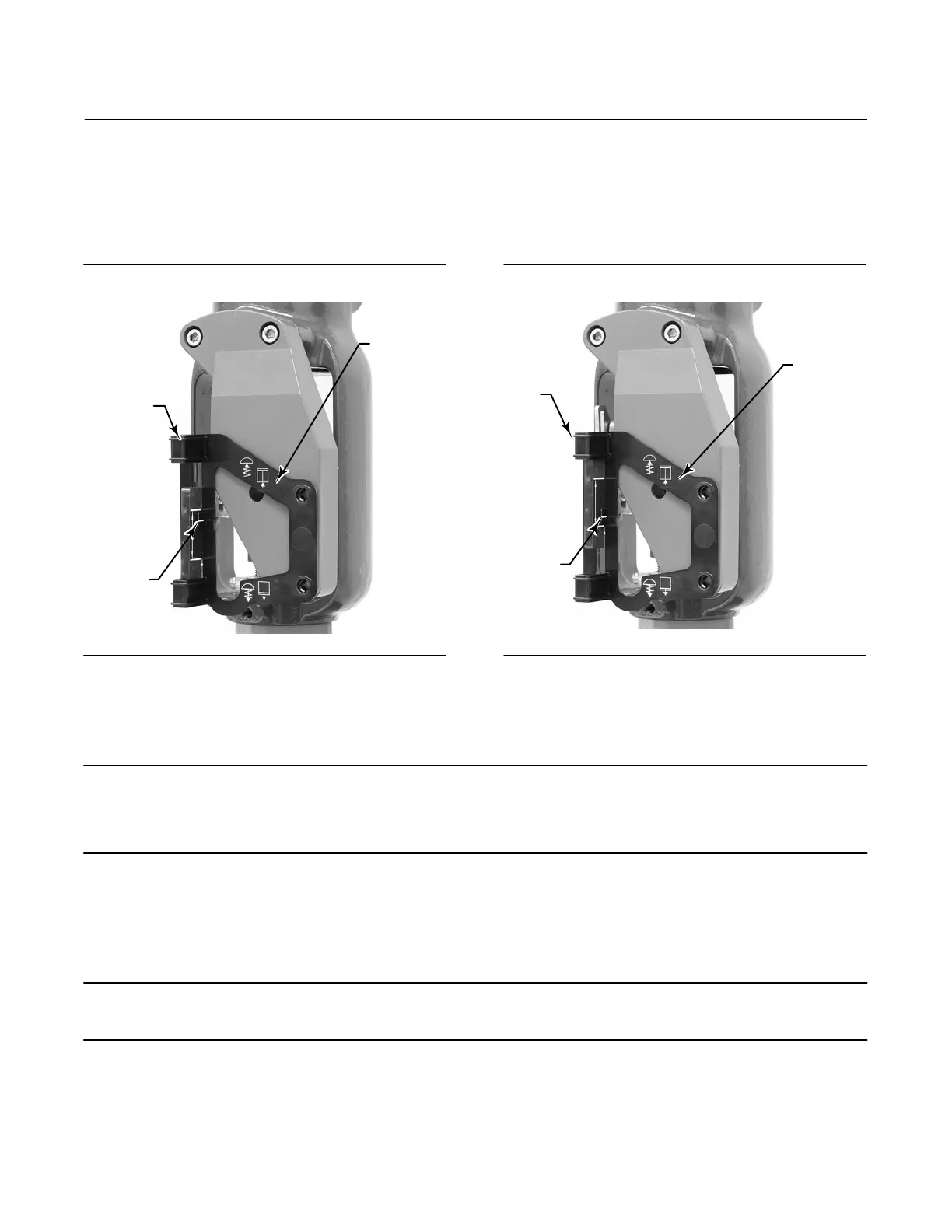
D For air‐to‐close actuators (e.g. Fisher 657) vertically align the magnet assembly so that the center line of the
alignment template is lined up as close as possible with the lower
extreme of the valid travel range on the
magnet assembly. The magnet assembly should be positioned so that the index mark in the feedback slot of the
DVC6200 housing is within the valid range on the magnet assembly throughout the range of travel. See figure 4.
Figure 3. Air‐to‐Open Magnet Assembly Alignment
W9718
ALIGNMENT
TEMPLATE
INDEX
MARK
RETAINING
SLOT
Figure 4. Air‐to‐Close Magnet Assembly Alignment
ALIGNMENT
TEMPLATE
W9719
INDEX
MARK
RETAINING
SLOT
6. Tighten the fasteners and remove the alignment template.
Note
Use a flat end hex key to tighten the magnet assembly fasteners to a torque of 2.37 N•m (21 lbf•in) for 4 mm screws, and
5.08 N•m (45 lbf•in) for 5 mm screws. For added security, especially in vibrating services, blue (medium) threadlocker may be
used on the fasteners.
7. Mount the digital valve controller to the mounting bracket, using the mounting bolts.
8. Check for clearance between the magnet assembly and the DVC6200 feedback slot.
Note
Ensure that there is clearance between the magnet assembly and the DVC6200 housing slot throughout the full range of travel.
9. For remote mount applications, proceed to page 17 for DVC6205 base unit mounting. Otherwise, proceed to
Step 2—Connect the Pneumatic Tubing on page 19.

 Loading...


