Instruction Manual
D103175X012
GX Valve and Actuator
April 2011
3
control of the process. Do not expose this product to service conditions or variables other than those for which the product was
intended. If you are not sure what these conditions are you should contact your Emerson Process Management sales office
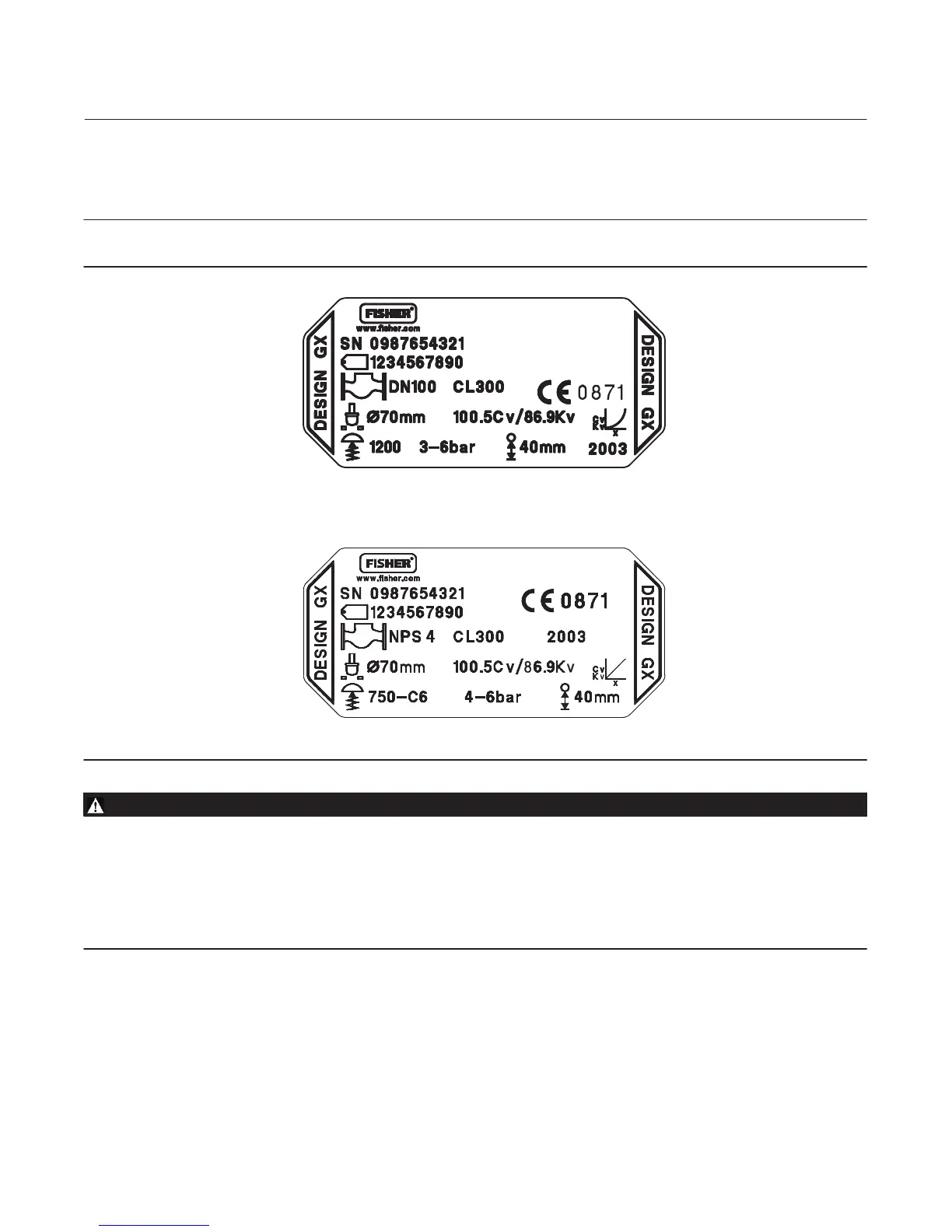
for more complete specifications. Provide the product serial number (shown on the nameplate, figure 2) and all other
pertinent information.
Figure 2. Fisher GX Nameplate Examples
GE41229-A
WITH SPRING INFORMATION
WITHOUT SPRING INFORMATION
GE01296‐G
WARNING
If you move or work on an actuator installed on a valve with loading pressure applied, keep your hands and tools away from
the stem travel path to avoid personal injury. Be especially careful when removing the stem connector to release all loading
on the actuator stem whether it be from air pressure on the diaphragm or compression in the actuator springs. Likewise
take similar care when adjusting or removing any optional travel stop. Refer to the relevant actuator Maintenance
Instructions.
If hoisting the valve take care to prevent people from being injured in case the hoist or rigging slips. Be sure to use
adequately sized hoists and chains or slings to handle the valve.
1. Before installing the valve, inspect it to be certain that the valve body cavity is free of all foreign material. Clean out
all pipelines to remove scale, welding slag and other foreign material.
2. The control valve assembly may be installed in any orientation unless limited by seismic criteria. However, the
normal method is with the actuator vertical above the valve. Flow through the valve must be in the direction
indicated by the arrow cast on the valve.
3. Use accepted piping practices when installing the valve in the pipeline. Use a suitable gasket between the valve and
the pipeline flanges.
 Loading...