FloBoss 103/104 Instruction Manual
2-8 Installation and Use Revised August-2017
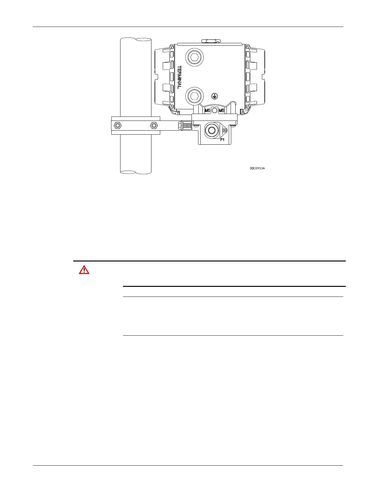
Figure 2-5. FB104 Mounting Option for ATEX unit
2.3.4 Meter Mounting (FloBoss 104)
The factory installs the Pulse Interface module to the base of the FB104.
Do not remove the FB104 from the Pulse Interface module; you may
damage cable connections between the interface and the FB100-Series
backplane.
Only the factory can install or remove the Pulse Interface module.
Cabling between the module and backplane can be easily damaged. The
module is not a user-serviceable component.
Note: The Pulse Interface module is not equipped to provide a
temperature input to the FB100 for gas compensations in AGA7
calculation. Instead, this input should come directly into the
FB104 from the built-in RTD input on the termination board.
If the FloBoss 104 has an optional LCD, orient the enclosure to ensure
that the display is visible after installation.
To mount the Pulse Interface module to the top of the rotary meter or
turbine meter:
To attach the FB104 and Pulse Interface module to a turbine meter,
attach the meter adapter at the base of the Pulse Interface module to
the meter housing with user-supplied 5/16-inch bolts (see Figure 2-6).

 Loading...